
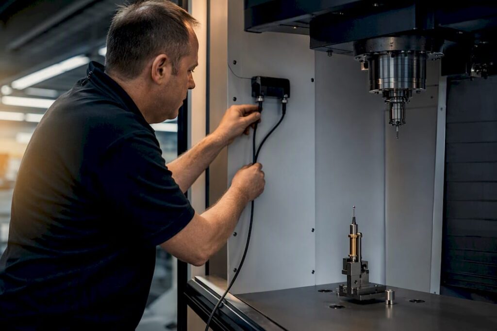
A CNC probing system is an on-machine measurement device, usually mounted in the spindle or on the table, that automates workpiece set-up, tool measurement and in-process inspection. It replaces manual dial indicators and edge finders with touch-trigger or scanning sensors that feed the control directly. The payoff is fewer setup errors, less scrap, and a real path to unattended machining once tool breakage and datum checks are handled automatically.
TL;DR:
- Touch-trigger probes are accurate and fast for simple setup tasks such as locating corners, bores, and checking tools, making them suitable for most shop-floor needs.
- Scanning probes provide detailed form and profile data but require longer cycle times, limiting their use to first-off inspections or critical features.
- Proper mounting location, stylus material, and environmental protection are critical; mismatched setups or contaminated styluses cause measurement errors.
- Reliable signal transmission depends on shop conditions, with wired being most stable, optical needing line-of-sight, and radio offering obstacle penetration but higher interference risk.
- Calibration, ongoing verification, and routine maintenance, including stylus replacement and environmental mitigation, are essential for consistent accuracy over time.
Table of Contents
- How do probing systems for CNC machines actually work?
- Which probe type and stylus suit your part?
- What’s inside a probing system, and how does it talk to the controller?
- What does probing actually save on the shop floor?
- How do you choose the right CNC probing system?
- How do you install, calibrate and maintain a probing system?
- How does probing data feed CAM, metrology software and robot cells?
- What causes probing errors, and how do you fix them?
- Engineer perspective: where probing actually pays for itself fastest
- Get your machine ready for probing with Anderson Group Australia
- Sources
- FAQ
How do probing systems for CNC machines actually work?
At its simplest, a probe is a switch. Touch it against a surface and it sends a trigger signal to the control at the exact moment of contact. The machine already knows where its axes are at that instant, so it captures a precise coordinate and updates a work offset, tool length, or diameter value without an operator lifting a finger.
There are two fundamentally different ways this happens, and mixing them up leads to buying the wrong probe for the job.
Touch-trigger probes fire a single discrete signal per contact. The stylus deflects a fraction of a micron, the sensor fires, the machine records a point. This is fast and accurate enough for the vast majority of shop-floor tasks: finding a corner, centring a bore, setting a Z zero, checking a tool for breakage.
Scanning probes work differently. Instead of one trigger per touch, they stay in continuous contact with the surface and stream a dense cloud of position data as they move. That’s slower and the hardware costs more, but it’s the only realistic way to capture form and profile data, checking a curved surface against CAD, verifying blend radii, or mapping distortion after heat treatment. Touch-trigger probes are accurate and efficient for setup and simple verification, while scanning probes trade speed for the continuous data needed for form measurement, and that tradeoff should drive your specification decision more than price alone.
Mounting location matters just as much as trigger type. A spindle-mounted probe sits in the toolholder like any other tool, picked up on a probing cycle call, and it measures the workpiece directly: datums, hole positions, part orientation on the fixture. A table-mounted toolsetter stays fixed in a known location and the tool comes to it, used to measure tool length and diameter, and to flag a broken or worn cutter before it ruins the next feature.
What does an actual trigger event look like in practice? The control runs a canned probing cycle (Fanuc’s is typically G65 with a macro variable set, Heidenhain and Siemens have their own cycle syntax), the axis moves at a controlled probing feed rate toward the target surface, the probe fires on contact, the control captures the axis position at that instant, and a macro variable or offset register updates automatically. No manual data entry, no transcription error.
The practical implications:
- Touch-trigger cycles typically run in seconds per point, making them viable even for high-volume production
- Scanning adds meaningful cycle time, so it’s usually reserved for first-off inspection or critical features rather than every part
- Spindle probes need a clear tool change slot and enough Z clearance to reach the part
- Toolsetters need to sit somewhere the tool can safely rapid to without crashing into fixturing
Automated systems reduce manual setup time, eliminate human data-entry errors, and can enable unattended machining through real-time process monitoring, which is the entire commercial case for fitting one in the first place.
Which probe type and stylus suit your part?
Not every probing job calls for the same hardware, and picking the wrong family wastes money in one direction or leaves accuracy on the table in the other.
Workpiece touch probes are the workhorse. They handle datum setting, hole and boss location, corner finding, and basic part presence checks. Most shops running mixed small-batch work will use this type more than any other.
Scanning probes earn their premium price on complex or freeform geometry, aerospace ribs, mould cavities, blended fillets, where a handful of touch points can’t characterise the surface. If your parts are mostly prismatic with flat faces and round holes, you probably don’t need one.
Non-contact laser and optical systems solve a different problem entirely: measuring tools that a physical stylus would damage, or measuring at speeds contact probing can’t match. Laser measuring systems can check tools at nominal speed and under harsh shop conditions, with protection and optics design critical to reliability, making them the better choice for fine-pitch drills, small taps, or any tool where contact deflection risks a false reading.
Toolsetters are the fourth family, dedicated to tool length, diameter, and breakage detection, and they’re often the single highest-ROI probe in the shop because a snapped end mill caught after the fact is scrap; caught before the next cut, it’s a five-second alarm.
Stylus choice deserves more attention than it usually gets:
- Ruby styli are the default because ruby is extremely hard, wear-resistant, and has a low friction coefficient against most metals, which keeps trigger repeatability tight over thousands of cycles
- Carbide or steel styli appear on cost-sensitive or abrasive applications where ruby’s brittleness under side-load becomes a liability
- Star and multi-ball stylus configurations let one probe reach features from multiple angles without a tool change, useful for undercuts and pocket walls
- Extended styli reach deep features but every extra millimetre of stem length amplifies deflection error, so longer isn’t automatically better
Environmental protection matters more than most spec sheets admit. Coolant flood, swarf, and thermal drift all degrade probe performance if the housing and seals aren’t rated for it. A probe that performs beautifully in a dry-cutting demo can drift or false-trigger in a flood-coolant aluminium shop, so match the ingress protection rating to your actual cutting environment, not the sales brochure’s test bench.
What’s inside a probing system, and how does it talk to the controller?
A probing system has four working parts, and understanding each one clarifies where reliability problems actually originate.
- The probe head houses the contact mechanism, kinematic or strain-gauge, that detects deflection and generates the trigger signal.
- The stylus is the replaceable contact tip; it’s the wear item and the first thing to check when readings drift.
- The probe interface or receiver unit (RPU) sits near the machine and converts the probe’s signal into something the controller can read, whether that’s a hardwired input, an optical receiver, or a radio module.
- The controller software layer runs the probing cycle, a pre-built macro that moves the axis, watches for the trigger, and writes the result to an offset or variable.
Signal transmission between probe and receiver is where shop-floor reality bites. Three methods dominate:
Wired probes are the cheapest and most reliable in principle, no interference, no batteries, but the cable limits spindle rotation and reach, so they’re mainly used on fixed toolsetters rather than spindle-mounted probes.
Optical transmission sends the trigger signal via infrared between probe and a receiver mounted somewhere with a clear sightline. It’s fast and immune to electrical noise, but it demands line-of-sight, so swarf, coolant mist, or a receiver mounted in the wrong spot will cause dropped signals.
Radio transmission penetrates obstacles and doesn’t care about sightline, which makes it the practical choice in enclosed machining centres with tight tool changers or awkward receiver placement. The tradeoff is susceptibility to electromagnetic interference from VFDs, servo drives, or other radio equipment nearby. Choice of transmission should be driven by workshop layout, obstacle density and interference sources, and it pays to test before committing to a wireless solution.
Controller integration follows a similar pattern across the major brands, even though the syntax differs. Fanuc controls typically call probing routines through a macro (commonly G65 with a program number and argument variables). Siemens Sinumerik uses its own cycle calls with parameter screens. Heidenhain TNC controls have dedicated touch probe cycles built into the conversational programming environment. Vendor-supplied probe cycle libraries provide pre-tested routines for common tasks like bore centring or corner finding, which cuts programming risk substantially, and running the cycle through CAM simulation before it ever touches a real part catches an approach vector heading straight into a clamp before it becomes an expensive mistake.
What does probing actually save on the shop floor?
The business case for probing rests on four measurable outcomes, and none of them require faith, they show up on the production log within weeks of commissioning.
Setup time drops sharply. Manually indicating a part on a fixture with a dial gauge and edge finder can eat 20 to 40 minutes on a complex casting. A spindle probe running an automated datum-finding cycle does the same job in under two minutes, and it does it the same way every time.
Significant setup time reductions on complex jobs are commonly reported once shops move from manual indicating to automated probing cycles, alongside measurable drops in scrap from dimensional errors caught before the first cut.
Tool measurement and broken-tool detection close a real gap. A toolsetter checks length and diameter after every tool change and can flag a snapped insert before the next feature runs into thin air. On unattended shifts, this single check is often what separates a finished batch from a bin of scrap parts discovered the next morning. Pairing probe-based tool checks with ongoing tool life monitoring tightens that safety net further.
In-process inspection enables closed-loop correction. A probe can measure a feature mid-cycle, compare it to nominal, and adjust the next operation’s offset automatically, catching thermal growth or fixture shift before it compounds across a batch.
Lights-out machining becomes realistic, but only with prerequisites in place. Reliable tool monitoring, consistent fixturing, and a probe cycle that verifies part presence before every operation are what make unattended running safe rather than reckless. Skip any of those and an unattended shift just produces scrap faster.
How do you choose the right CNC probing system?
Specification starts with your parts, not the probe catalogue. Work backwards from what the part actually needs.
Match accuracy and repeatability to your tolerance band, not the tightest number on the spec sheet. A probe rated to 1 micron repeatability is wasted on parts held to ±0.1mm on a general-engineering job; it’s essential on aerospace bores held to a few microns. Tie the decision to your actual tolerance requirements and whatever SPC targets your quality system runs against, because over-specifying accuracy mostly just inflates the invoice.
Check stylus reach against your actual fixturing, not a clean CAD model. Clamps, risers, and coolant nozzles all create obstructions a probe has to navigate around, and a stylus that’s too short to clear a fixture wall is a redesign you don’t want to discover after the probe arrives. This is where zero-point fixturing systems genuinely earn their keep, since consistent datum repeatability upstream makes the probing cycle downstream far more predictable.
Test transmission reliability in your actual environment before you commit. Radio and optical probes both have failure modes tied to the specific shop they’re installed in, and a demo at a trade show tells you nothing about how the signal behaves next to your particular VFDs and welding bay.
Budget realistic cycle-time impact. Probing cycles add time to every part program, typically seconds for touch-trigger setup checks, considerably more for scanning inspection. Factor that into throughput calculations rather than treating probing as a free efficiency gain.
Ask vendors the questions that actually predict five years of ownership, not five months:
- What’s the calibration support model, on-site technician, remote diagnostics, or self-service with a reference artefact?
- What’s typical lead time on stylus and battery spares, and do you stock locally?
- Is operator training included, or a separate line item?
- What’s the warranty on the receiver unit versus the probe head itself, since they usually fail on different timelines?
- Can the probe cycle library be customised, or are you locked into the vendor’s canned routines?
Pro Tip: Run a short on-site transmission test with your actual radio or optical probe candidate before signing the purchase order. Shop floors are noisy in ways a supplier’s demo room never replicates, and a 30-minute field test costs nothing compared to discovering signal dropouts after installation.
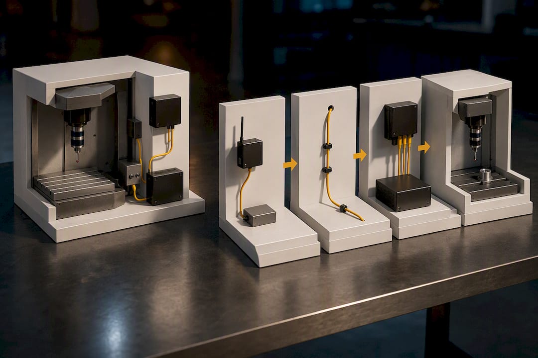
Commissioning timelines typically run one to three weeks depending on whether the probe is factory-fitted to a new machine or retrofitted to existing kit, with retrofit jobs taking longer due to cable routing, receiver placement, and control integration work.
How do you install, calibrate and maintain a probing system?
Probe installation should be treated as a sequence of steps, not a single event, because skipping a step can cause accuracy problems later.
- Survey the site before anything ships. On a retrofit, check available I/O on the controller, confirm spindle taper compatibility for a spindle probe, and map the shop floor for radio or optical interference sources, other CNC drives, welding bays, overhead cranes with VFDs.
- Plan cable and receiver placement early. Optical receivers need a genuine, unobstructed sightline to the probe’s resting and firing positions; radio receivers need placement clear of the densest interference sources identified in the survey.
- Run the initial calibration routine against a certified reference artefact, a calibrated sphere or ring gauge, to establish the probe’s true trigger offset in all relevant axes.
- Verify with a repeatability test, touching the same point repeatedly and checking the spread of recorded positions against the manufacturer’s stated tolerance.
- Run a small batch of production parts and check the probed dimensions against a CMM or trusted gauge to confirm the probe’s readings map correctly onto finished part geometry, not just onto the reference artefact.
- Document a maintenance schedule. Stylus wear is the most common failure point; a bent or worn ruby ball changes trigger repeatability well before it becomes visually obvious.
- Re-verify after any service event, a crash, a spindle rebuild, or a control software update, using the same reference-artefact routine from commissioning.
Pairing probing repeatability checks with a ballbar test and a small batch of production parts gives high confidence that probe measurements map correctly onto finished geometry, which is exactly the kind of verification step that catches a subtle installation error before it costs you a batch of scrap parts. It’s worth running the same ballbar and reliability verification discipline you’d apply to the machine’s general geometry checks.
Pro Tip: Keep a spare stylus of every type on the shelf, not just on order. Stylus wear is gradual and easy to miss until a batch starts failing dimensional checks, and a five-minute swap beats a half-day wait on a courier.
Routine quick checks between full calibrations don’t need to be elaborate: a daily visual inspection of the stylus tip for chips or wear, a weekly repeatability spot-check against a known reference point, and a check that the receiver unit’s status light or diagnostic screen shows no fault flags.
How does probing data feed CAM, metrology software and robot cells?
Probing only pays off fully when the data it generates actually goes somewhere useful, rather than disappearing into a machine’s local memory after the cycle finishes.
Most CAM systems, including NX CAM and similar packages, let you generate and simulate probe paths alongside the machining toolpath, so the approach vector, stylus clearance, and retract moves get checked against the fixture model before anything runs on the actual machine. That simulation step is cheap insurance against a crash.
- Probed results can export directly into metrology or SPC systems for trend tracking and process capability reporting, closing the loop between measurement and quality documentation
- That data flow pairs naturally with broader MES integration efforts, since probe results are exactly the kind of shop-floor data an MTConnect or OPC UA pipeline is built to carry
- Robot cells extend the same principle: six-degree-of-freedom datum functions let a robot locate parts and tools accurately relative to the cell, reducing manual interventions and supporting autonomous production
- Cell layout and robot tending arrangements affect how reliably a robot-mounted probe can reach its datum points, so cell layout planning deserves attention before the probe hardware is finalised
The practical limitations are worth naming honestly. Some CAM probing modules carry their own licence cost on top of the base seat. Probe cycles add real cycle time to every part, which matters on high-volume, low-margin work. And none of this data flow means anything if the underlying fixturing isn’t repeatable, since a probe faithfully measuring an inconsistently clamped part just produces precise data about an imprecise setup.
What causes probing errors, and how do you fix them?
Most probe problems trace back to one of four root causes, and working through them in order usually finds the fault before you need to call a service technician.
- False triggers (the probe fires when it shouldn’t) usually point to a damaged or contaminated stylus, loose mounting, or vibration from a nearby machine. Check the stylus first, physically inspect it for chips, deformation, or coolant residue in the contact mechanism.
- No trigger at all often means a transmission failure rather than a probe fault: check battery level on wireless probes, confirm optical line-of-sight hasn’t been blocked by a new fixture or swarf buildup, and verify the receiver unit is powered and showing a healthy status light.
- Noisy or inconsistent signal on radio probes frequently traces to electromagnetic interference from nearby VFDs or servo drives; try relocating the receiver or switching to a different radio channel if the probe supports it.
- Offset drift over time without any visible stylus damage suggests thermal expansion in the machine structure itself, run a repeatability test at operating temperature rather than cold, since a probe calibrated on a cold machine will show apparent drift once the spindle and structure warm up.
- When in doubt, run a dry simulation of the probing cycle in CAM before touching the real machine again; this isolates whether the fault is in the program logic or the hardware.
Environmental mitigation, better sealing against coolant, relocating a receiver away from an interference source, adding a light shield against ambient light on optical systems, solves a surprising share of these issues without any hardware replacement. If a repeatability test still fails after stylus replacement and environmental fixes, that’s the point to call the manufacturer’s service line rather than keep troubleshooting blind.
Engineer perspective: where probing actually pays for itself fastest
The shops that get the fastest return aren’t the ones running the highest-tech probe, they’re the ones running the most repetitive setups. High-mix, low-volume job shops with constantly changing fixtures see the setup-time savings almost immediately, because that’s where manual indicating eats the most hours. A dedicated production line running the same part for months sees less dramatic setup gains but wins big on tool-breakage detection during unattended shifts.
The most common blocker isn’t the hardware, it’s programming discipline. A probe cycle written once and never revisited becomes a liability when tooling or fixturing changes and nobody updates the macro. Build a review step into your engineering change process, not just your initial commissioning.
For a first pilot, track three numbers over 90 days: setup time per changeover, scrap rate tied to dimensional error, and unplanned downtime from broken-tool events. Those three numbers will tell you, honestly, whether the investment is working before you scale it across the rest of the shop.
— Anderson
Get your machine ready for probing with Anderson Group Australia
Anderson Group Australia gives manufacturers a direct path to probe-ready machines instead of retrofitting an ageing centre and hoping the geometry holds up. Every metal machining centre in the range can be specified with probing integration from the factory, so you skip the survey-and-retrofit cycle entirely and get a machine that’s already commissioned for automated setup and tool measurement.

That matters most for shops weighing a new machine against bolting a probe onto an older one: factory integration avoids the interference surprises and cable-routing compromises that dog a retrofit, because the wiring, receiver placement, and controller configuration are sorted before the machine ever reaches your floor. If your work spans multiple materials, the wood machinery and advanced materials machining ranges follow the same approach, with probing considered from the design stage rather than added on afterward.
Browse the full machines lineup and get in touch for a site survey, commissioning plan, and operator training tailored to your shop’s actual layout and part mix.
Sources
- Probing and tool measurement systems for machine tools
- Capability of measurement with a touch probe on CNC …
- Laser measuring system for tool setting and monitoring (BLUM)
FAQ
What Is a Probe in CNC?
A CNC probe is an on-machine sensor, mounted in the spindle or on the table, that detects contact with a workpiece or tool and sends a trigger signal the control uses to update coordinate offsets, tool dimensions, or inspection data automatically.
How Much Does a Haas Probe Cost?
Haas probing packages vary by machine model and probe type, with pricing set by the dealer network rather than published as a fixed figure; check current specifications and pricing directly through Haas or your machine tool dealer. Anderson Group Australia’s own machine and probe integration pricing is available on request through its machines page.
Why Are CNC Probes Ruby?
Ruby is extremely hard, resists wear from repeated contact, and has a low friction coefficient against most workpiece metals, which keeps trigger repeatability consistent over thousands of measurement cycles compared to softer stylus materials.
What Is a Renishaw Probe?
Renishaw manufactures a range of touch-trigger, scanning, and toolsetting probes for CNC machine tools, along with the receiver units and probe cycle software that integrate them with major machine controllers, and its technical documentation covers the core mechanics behind most on-machine probing systems in use today.
Do I Need a Scanning Probe or a Touch-Trigger Probe?
Touch-trigger probes handle the majority of setup, datum finding, and tool measurement tasks efficiently; scanning probes are only necessary when you need continuous surface or profile data for form inspection against a CAD model.