
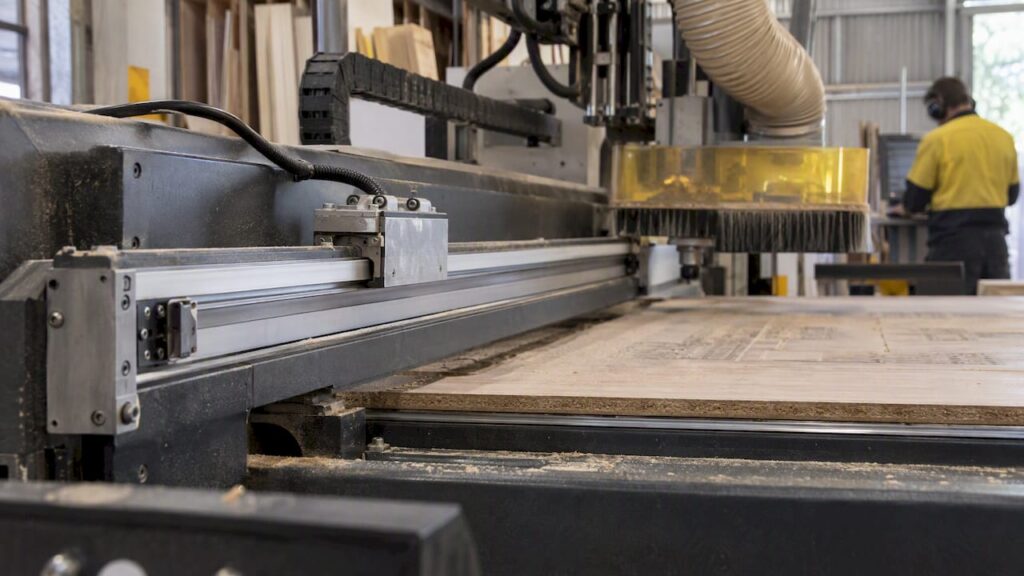
A linear scale, or linear encoder, gives the CNC controller the actual axis position so motion matches the program exactly, rather than relying on motor steps alone. The main trade-off sits between resolution and environmental tolerance: higher resolution optical scales demand cleaner conditions, while magnetic and inductive types trade some accuracy for durability in dust and vibration. The rest of this article covers specifications, mounting, maintenance and selection for nesting and panel processing shops.
TL;DR:
- Absolute scales report position immediately after power on, while incremental models require homing; match SSI or BiSS and differential TTL outputs to the controller.
- Optical glass delivers the highest resolution in clean cells, but sealed magnetic scales better withstand woodworking dust, while inductive designs suit heat and vibration.
- For production tolerances, prioritize repeatability over headline resolution, and verify accuracy, interpolation error, scale length, mounting tolerance, traverse speed, and update rate.
- Mount scales on thermally matched rigid structures, check alignment and readhead gap across the full stroke, and separate signal cables from motor power cables.
- Shift long drift usually signals thermal mismatch, while intermittent faults point to cable routing, connectors, or earthing; clean scales routinely to prevent lost counts.
Table of Contents
- Linear scale vs linear encoder: absolute and incremental explained
- How linear scales work: optical, magnetic and inductive types
- Key specifications that determine CNC accuracy
- Mounting and alignment practices that protect accuracy
- Troubleshooting a linear scale on the shop floor
- Choosing a linear scale for nesting and panel processing
- Anderson’s approach to matching scales, machines and support
- Get your machine specified to match the right feedback system
- FAQ
- Sources
Linear scale vs linear encoder: absolute and incremental explained
A linear scale is the physical measuring element: a glass, steel or magnetic strip carrying a graduated pattern. The readhead, sometimes called the encoder, rides along that scale and converts the pattern into an electrical signal the controller reads as position. Together they form a closed loop feedback system distinct from the servo motor’s own internal sensor.
- Incremental scales output pulses counted from a reference point, needing a home or reference mark on power up.
- Absolute scales encode position directly in the signal, so the controller knows exact location immediately after power on, with no homing cycle.
Incremental systems are common in retrofit digital readouts (DROs) on older machines, where cost matters more than instant position recovery. Absolute scales are increasingly standard on OEM‑fitted nesting and panel processing machines, where production uptime makes a homing delay unwelcome. MEM07028 sets out the operator tasks, including verifying programs and using measuring instruments, that assume this feedback loop is working correctly before a job starts.
How linear scales work: optical, magnetic and inductive types
Each scale technology reads position differently, and the choice shapes how the machine performs in a working shop.
- Optical glass scales use a light source and photodetector reading fine etched graduations, giving the highest resolution of the common types but suffering accuracy loss when dust, coolant mist or swarf coats the glass.
- Magnetic tape scales read a magnetised strip through a sealed readhead, tolerating dust and moisture far better than optical designs, at a modest cost to absolute linearity.
- Inductive scales, including resolver based designs, use electromagnetic coupling rather than light or magnetism, and hold up well in harsh thermal and vibration conditions on heavier machine tools.
Output format matters as much as sensing technology. Absolute scales typically communicate over serial protocols such as SSI or BiSS, while incremental scales commonly use differential TTL signals. Mixing protocols incorrectly between scale and controller is a frequent commissioning error.
Electromagnetic compatibility, contamination ingress and thermal stability all affect which type suits a given install. A nesting cell running multiple spindles and dust extraction close together faces more electrical noise than an isolated single axis retrofit, which pushes the decision toward shielded, sealed designs over exposed optical strips.
Key specifications that determine CNC accuracy
Four figures decide whether a scale will hold a part’s tolerance in production: resolution, accuracy, repeatability and interpolation error. Resolution is the smallest position increment the system can report. Accuracy, sometimes called linearity error, describes how far a reported position can deviate from true position across the scale’s length. Repeatability measures how consistently the system returns to the same point, which matters more than raw resolution for most production work. Interpolation error is the rounding or estimation error introduced when the readhead electronics interpolate between physical graduation marks.
- Scale length and mounting tolerance affect how closely the scale can track the machine’s actual travel without binding.
- Scale interval and minimum delivery, as defined in NMI M‑1, set the baseline terminology for reading error that specification sheets reference.
- IP rating, coefficient of thermal expansion, maximum traverse speed and encoder update rate all limit how the scale performs under real shop conditions, not just on a test bench.
Repeatability, not headline resolution, is usually the figure that determines whether a batch of parts stays within tolerance across a full shift. Our CNC tolerances guide tied to ISO 2768 explains how these tolerance bands map back to the specifications above.
Mounting and alignment practices that protect accuracy
Installation quality determines whether a correctly specified scale actually delivers its rated accuracy.
- Mount the scale on a rigid structure matched thermally to the machine bed, since mismatched expansion rates introduce drift that no amount of recalibration will fully remove.
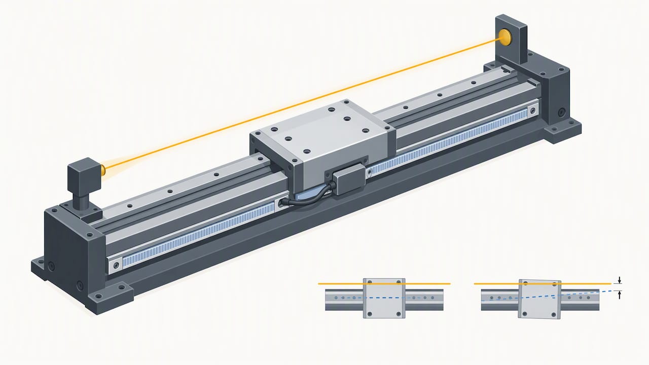
- Check parallelism and squareness against the axis of travel, and confirm the readhead gap sits within the manufacturer’s specified range across the full stroke to avoid parallax error.
- Route signal cables away from motor and spindle power cables, earth the system correctly for electromagnetic compatibility, and fit proper strain relief at every connector.
Pro Tip: Check readhead gap at both ends of travel, not just the middle, since a scale that looks aligned at mid stroke can still pinch or lift at the extremes.
For a deeper look at verification technique once the scale is mounted, our laser‑first alignment guide covers the checks engineers use to confirm a machine tool is tracking true before it returns to production.
Troubleshooting a linear scale on the shop floor
Most position faults trace back to one of a handful of causes, and a quick inspection usually narrows the field before any disassembly.
- Drift over a shift often points to thermal mismatch between the scale and the machine structure rather than a failing readhead.
- Noise or intermittent faults usually trace to cable routing, a loose connector or inadequate earthing near variable frequency drives.
- Missing counts suggest contamination on an optical scale or physical damage to the graduated strip.
- Routine cleaning of the scale and readhead, checked against the manufacturer’s schedule, catches most contamination issues before they cause lost counts.
- When simple move tests and known length checks don’t resolve a discrepancy, escalate to laser or ballbar alignment and controller diagnostics, as outlined in our 90 day reliability and ballbar testing plan.
Choosing a linear scale for nesting and panel processing
Dust is the dominant environmental factor in most woodworking shops, which shifts the priority away from the highest theoretical resolution toward sealed, dust tolerant designs.
- Favour sealed absolute or magnetic tape scales where dust extraction can’t guarantee a clean environment around the axis.
- Reserve optical glass scales for cleaner cells or applications where positional accuracy requirements genuinely need the extra resolution.
- Match resolution and repeatability targets to the part tolerances the shop actually produces, using a guide such as our tolerance mapping resource rather than specifying beyond what the job needs.
- Weigh serviceability and local spare parts access alongside raw specification, since a scale that can’t be replaced quickly costs more in downtime than it saves in accuracy.
- Keep coolant and mist exposure in mind on mixed material shops; our coolant selection guide covers splash risk relevant to nearby feedback hardware.
Anderson’s approach to matching scales, machines and support
We supply Wood Machinery including the Genesis PLUS nesting platform, configured with feedback systems suited to panel processing and nesting work, alongside Metal Machinery for aluminium and steel applications through our Focaseiki range.
- We match encoder type to the machine’s working environment before it leaves the factory floor.
- We support installation, calibration checks and preventive maintenance scheduling through our service team, following professional maintenance guidance such as our CNC preventive maintenance checklist.
- We stock parts to support ongoing servicing once a machine is in production.
| Shop need | Recommended encoder characteristic |
|---|---|
| Dusty nesting cell, high uptime priority | Sealed absolute or magnetic tape scale |
| Cleaner cabinetry cell, tight tolerance work | Optical glass scale with high resolution |
| Mixed metal and wood production | Inductive or sealed type matched to Focaseiki or wood machine spec |
Get your machine specified to match the right feedback system
We help kitchen, cabinet, joinery and furniture manufacturers choose machinery configured with the feedback systems their production actually needs, matching encoder type to shop environment before the machine ships rather than after.

If nesting or panel processing accuracy is the goal, our Genesis PLUS nesting CNC machine page has the detail to start a conversation, or you can request a quote and talk through your application with our team.
FAQ
What is the meaning of a linear scale?
A linear scale is the physical measuring element in a position feedback system, a graduated strip that a readhead reads to report exact axis position to the CNC controller. It works together with the readhead and controller interface as a closed loop system, as distinct from a motor’s own internal sensor.
What are the four types of encoders?
Common CNC encoder types include optical, magnetic, inductive and laser interferometric systems, each sensing position differently and suiting different shop environments. Optical offers the highest resolution, magnetic and inductive types tolerate dust and vibration better, and laser interferometers are typically used for calibration rather than everyday machine feedback.
What is linear interpolation in CNC machining?
In encoder terms, interpolation refers to the electronics estimating position between physical graduation marks on the scale, which introduces a small interpolation error figure specified by the manufacturer. In motion programming, linear interpolation separately describes the controller moving an axis in a straight line between two programmed points.
What does a linear encoder do?
A linear encoder reads the physical scale and converts the mechanical position into an electrical signal the CNC controller uses to verify and correct axis position in real time. This closed loop feedback lets the machine confirm it has actually reached the commanded position, rather than assuming it based on motor steps alone.