
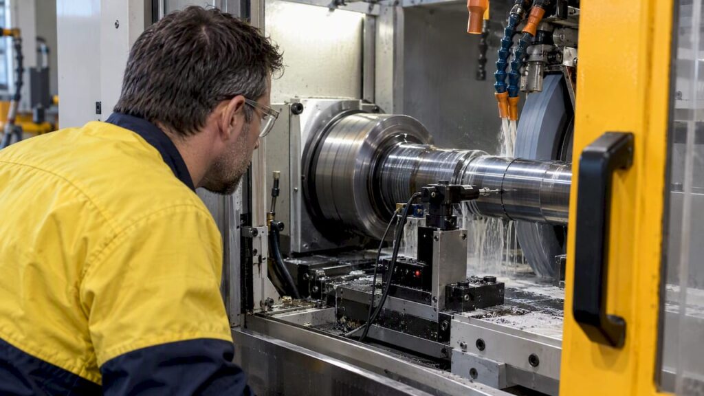
In-process gauging measures parts while they are still being machined and feeds real-time data to the controller so the process can compensate automatically, cutting scrap and lifting yield. It relies on traceable measurement, with dimensional calibration in Australia running back to the National Measurement Institute (NMI) through NATA-accredited laboratories. CNC machinery is the platform that this kind of gauging runs on, so getting the fundamentals right matters to every shop considering it.
TL;DR:
- On-machine gauging commonly supports adaptive finishing and lights-out production by providing real-time measurements without stopping the process.
- Choice of technology depends on accuracy needs, cycle-time constraints, environmental exposure, and maintenance capacity, with options including air, contact, touch-trigger, and scanning probes.
- Calibration traceability from the National Measurement Institute or accredited labs is essential to ensure measurement validity, following ISO standards for uncertainty and verification.
- Proper mounting, re-mastering triggers, and routine maintenance are critical for reliable sensor operation, especially near abrasive materials requiring safety controls like wet suppression.
- When an on-machine gauge’s measurement uncertainty exceeds the feature tolerance, a coordinate measuring machine should be used instead of in-process gauging.
Table of Contents
- Where in-process gauging fits in machining and grinding
- Common in-process gauging technologies and their trade-offs
- How closed-loop feedback drives intelligent process control
- Calibration, traceability and standards to follow
- Implementation checklist: mounting, mastering, maintenance and safety
- Validating on-machine measurement capability: a short how-to
- How we help you put in-process gauging on the machine
- FAQ
- Sources
Where in-process gauging fits in machining and grinding
In-cycle gauging typically checks diameter, length and critical form features without stopping the part or pulling it off the machine. On grinding operations, it is especially common to track diameter continuously as stock comes off, so the wheel feed can be trimmed before a part drifts out of tolerance.
This approach suits adaptive finishing passes, where the final cut depends on a live measurement rather than a fixed program value, and automated verification cycles that confirm a feature before the next operation starts. It is also central to lights-out production, where no operator is present to catch a drifting process overnight.
The alternative, intermittent off-machine inspection, only tells you about the one part just measured. By the time a trend shows up on a sample plan, several parts may already be out of spec. In-process gauging catches that drift while the part is still in the machine, which is the main reason production shops adopt it over periodic sampling alone.
Common in-process gauging technologies and their trade-offs
Four technology families cover most shop-floor needs, and each suits a different combination of geometry, tolerance and environment.
- Air gauging is non-contact and fast, well suited to bores and close-tolerance diameters, but its response slows as back-pressure drops near the end of a cut, so a longer time constant can mask rapid final changes if nozzle geometry and setpoints are not validated at production feed rates.
- Contact gauges give continuous readings and work well on grinding diameters, but the probe tip or contact element wears with use and needs periodic re-mastering to stay accurate.
- Touch-trigger probes take discrete on-machine readings between or within cycles, useful for verifying a feature without a separate inspection step.
- Scanning probes capture dense point data for form and profile, supporting adaptive compensation, but require careful synchronisation between probe motion and machine dynamics to avoid geometric artefacts.
Choice generally comes down to accuracy needed, cycle-time impact, exposure to chips and coolant, and how much maintenance the shop can sustain.
How closed-loop feedback drives intelligent process control
Once a gauge takes a reading, that value has to become something the control acts on. In practice this means an offset update: the gauging system passes a measured deviation to the CNC control, which adjusts the next tool position or feed to correct for wear or drift. Cycle timing and the communications interface between gauge and control both affect how quickly that correction can happen.
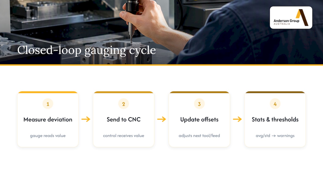
Most installations also run simple statistics alongside the raw offset, tracking a running average and standard deviation of recent readings rather than reacting to a single point. Warning and wear thresholds are set against those statistics, so the system can flag a tool change or a re-mastering event before parts actually go out of tolerance. For the broader tool-wear side of this, our piece on controller data and tool-life monitoring covers how that data complements dimensional gauging.
Done well, this reduces scrap, cuts how often an operator needs to intervene, and lets one gauging system update offsets across a run of parts rather than checking each one by hand. The trade-off is integration effort: communications between gauge and control need to be reliable, the added measurement step has to fit the cycle-time budget, and the whole loop needs validating before it is trusted for production tolerances.
Calibration, traceability and standards to follow
Any in-process gauging claim is only as good as the calibration behind it. In Australia, that means a traceability chain running from NMI primary length and dimensional standards through NATA-accredited calibration laboratories, which issue results under ISO 17025.
When budgeting uncertainty, a common rule of thumb keeps the reference standard’s uncertainty at roughly a third of the instrument’s maximum permissible error, so the reference does not become the limiting factor in the measurement. Decision rules for accepting or rejecting a part near a tolerance limit should follow ISO GPS guidance and the ISO 14253 framework rather than an ad hoc house rule.
For in-service verification of measuring instruments themselves, NITP 0 sets out general test procedures, covering visual inspection, required data collection and how results get documented against applicable MPEs. Practically, that means keeping calibration certificates, verification marks and a re-verification schedule on file for every gauge in production use, not just the ones that look suspect.
Implementation checklist: mounting, mastering, maintenance and safety
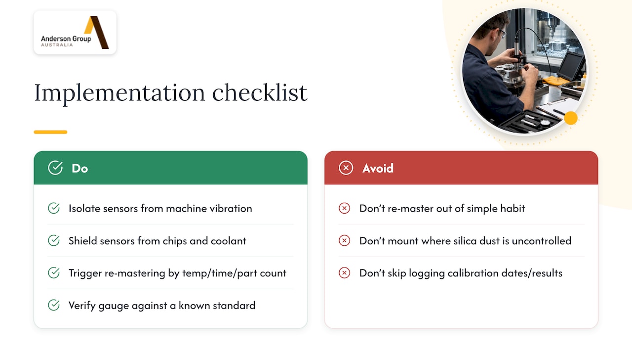
A gauging system is only as reliable as its mechanical setup. Mount sensors so they are isolated from machine vibration, and shield them from chip and coolant ingress, since both are common causes of erratic readings that get blamed on the gauge rather than the installation.
Re-mastering needs a trigger, not just a habit. Temperature drift, elapsed time and part count are the three usual triggers, and the right limit for each is typically found by running a part program on loop and recording how the gauging reading changes against temperature or cycle count for that specific material and geometry.
A basic maintenance routine covers wear monitoring on contact elements, periodic verification against a known standard and a simple log of calibration dates and results. Where the process involves engineered stone or other silica-containing materials, WHS guidance requires controlled processing through wet suppression, on-tool extraction or effective local exhaust ventilation, which constrains where and how a gauging sensor can be mounted near the cutting zone.
Pro Tip: Log the gauge’s own drift against a fixed reference part before trusting it to chase a tight production tolerance.
Validating on-machine measurement capability: a short how-to
Capability and applicability are not the same thing. Capability asks whether a gauge can repeat a measurement within an acceptable spread; applicability asks whether that capability is good enough for the specific tolerance and feature at hand, and the two can give different answers for the same setup.
A workable validation path starts by building an uncertainty budget for the measurement, then running a capability check such as the ISO 22514-7 approach or a comparable MSA-style study, and comparing the tolerance-to-uncertainty ratio against your acceptance criterion. Recent analysis of on-machine measurement found that ISO 22514-7 capability metrics and EN ISO 14253 applicability rules can reach different conclusions for the same CNC setup, so validate before relying on either in isolation. When the ratio fails to clear your criterion, or the feature’s tolerance is tight relative to the gauge’s own uncertainty, escalate to a CMM rather than stretching an on-machine check beyond what it can support.
How we help you put in-process gauging on the machine
We commission CNC probing systems for factory fit or retrofit, whether that is a new machine order or an upgrade to equipment already on your floor. Our factory fit or retrofit probing guide covers how that commissioning process works in more detail.

Most of what we sell goes to kitchen, cabinet, joinery and furniture manufacturers, so nesting and panel-processing machines such as those on our Wood Machinery page are where in-process gauging most often gets paired with an Anderson machine. For metal and aluminium milling, Focaseiki machining centres cover a separate range worth checking against your tolerance and material.
- We supply the machine, commission the probing and provide parts and servicing afterward.
- We do not perform subcontract cutting or machining ourselves.
- Specifications are confirmed against the actual product page before you order.
| What we provide | What it covers |
|---|---|
| Machine supply | Wood, metal and advanced materials machinery lines |
| Probing commissioning | Factory fit or retrofit of CNC probing systems |
| Ongoing support | Parts and servicing after installation |
If you are weighing up a gauging retrofit or a new machine with probing built in, get in touch to discuss your application and we can talk through which setup matches your parts.
FAQ
What is in-process gauging in simple terms?
In-process gauging measures a feature such as a diameter or length while the part is still in the machine, rather than after it is removed for separate inspection. The reading can then be used to adjust the next cut automatically rather than waiting for a scrapped or reworked part to show the problem.
How does in-process gauging improve CNC machining quality?
It feeds measured deviations back to the control as offset updates, so tool wear and thermal drift get corrected cycle by cycle instead of accumulating. This closed-loop approach, covered in tool-life and controller data monitoring, reduces how often an operator needs to step in and catch a drifting process.
Why does calibration traceability matter for in-process gauges?
Traceability through NMI and NATA-accredited laboratories means a gauge’s readings can be trusted against a documented chain of reference standards rather than an isolated claim. Without that traceability, there is no defensible basis for accepting or rejecting a part near its tolerance limit under ISO 14253 decision rules.
When should a shop use a CMM instead of on-machine gauging?
A CMM is the better choice when an uncertainty budget and capability check show the on-machine gauge’s tolerance-to-uncertainty ratio does not clear your acceptance criterion for that feature. Recent assessment of on-machine measurement systems shows this can vary feature by feature on the same machine, so the decision is made per application, not once for the whole shop.
Does in-process gauging affect machine safety requirements?
Yes, particularly when gauging equipment sits near abrasive processing of engineered stone or other silica-containing materials, where WHS guidance mandates controls such as wet suppression or local exhaust ventilation. Sensor mounting and cabling need to work within those controls rather than around them.
Sources
- Length and dimensional measurement services | Department of Industry Science and Resources
- Work safely with crystalline silica and engineered stone (SafeWork NSW)
- Assessment of CNC machines as on-machine measurement systems