
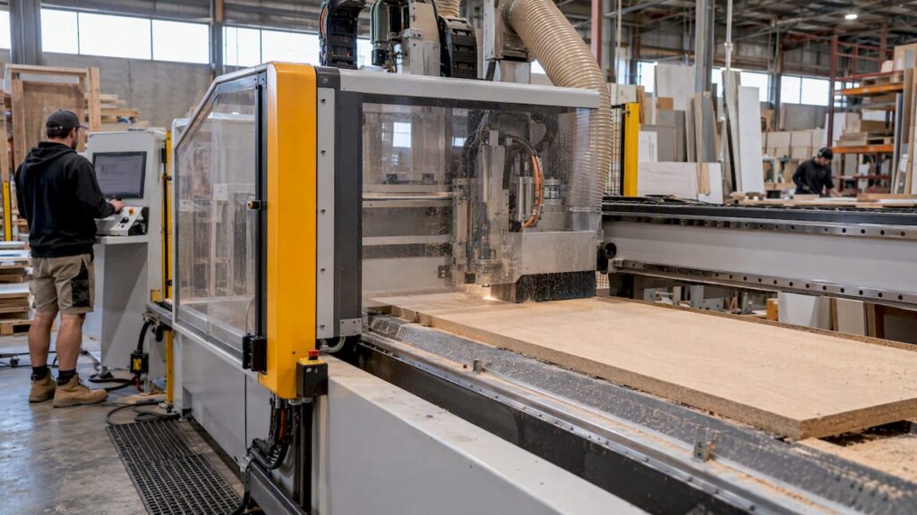
Linear motors are direct-drive feed drives that deliver higher acceleration, faster settling and sub-micron dynamic tracking for CNC axes, at the cost of more active thermal management and different maintenance trade-offs. They suit applications where dynamic accuracy and cycle time matter more than upfront cost, provided the machine builder addresses thermal drift, swarf ingress and safety integration under AS/NZS 4024.1503:2026. Experimental work from euspen backs the dynamic case; the sections below unpack each trade-off.
TL;DR:
- Linear motors offer significantly faster settling times and improved dynamic tracking, particularly benefiting high-speed nesting and adaptive milling applications.
- Proper thermal management, including liquid cooling and real-time modeling, is essential to prevent heat-induced geometric errors during continuous operation.
- Safety features such as Safe Torque Off must be integrated into the drive system, with verification during commissioning to ensure compliance with relevant standards.
- Retrofitting existing ball-screw axes requires verifying guideway stiffness and available space for the magnet track to prevent costly mismatches and performance issues.
- They are an ideal choice for applications where dynamic accuracy and cycle times outweigh initial costs, but are less suited for low-cost, heavy-duty roughing or grinding tasks.
Table of Contents
- How direct-drive linear motors work and which type to specify
- What to specify in the hardware and control stack
- Linear motor versus ball screw: what the numbers show
- Managing thermal drift in linear motor feed axes
- Matching linear motors to the right CNC application
- Safety standards and functional-safety integration
- Anderson Group Australia: where linear-motor expertise fits our range
- Talk to us before you commit to a feed-drive spec
- FAQ
- Sources
How direct-drive linear motors work and which type to specify
A linear motor replaces the rotary motor, coupling and ball screw with a primary (the coil assembly, usually the mover) and a secondary (the magnet track or reaction rail), so thrust acts directly on the carriage with no mechanical transmission. Moving-magnet designs keep the coil stationary and move the lighter magnet track, which suits long travels; moving-coil designs put the winding on the carriage and are common on shorter, high-dynamic axes.
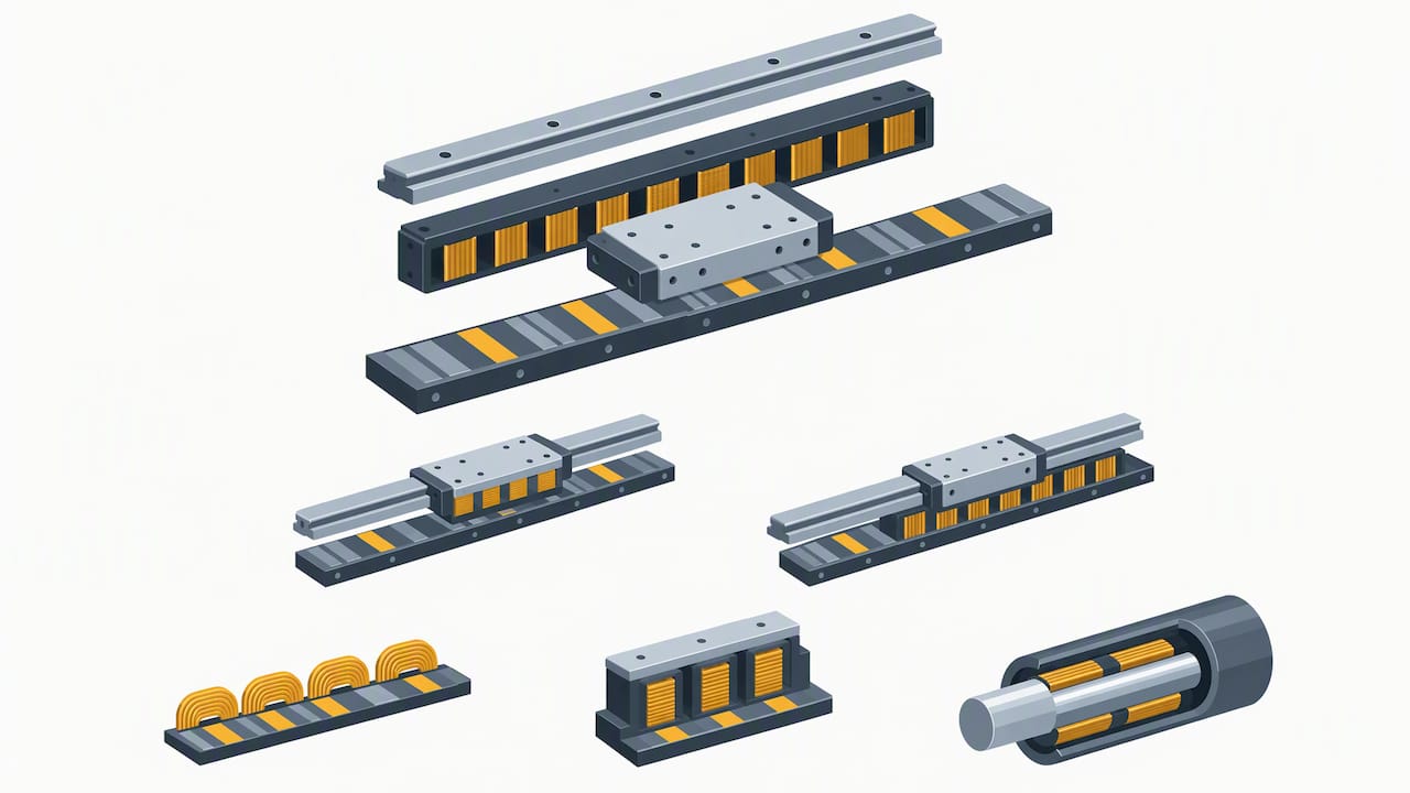
Ironless (coreless) motors have no iron in the coil, which removes cogging and gives smoother low-speed motion, but they produce less force per frame size. Iron-core motors pack in more force density for the same footprint, at the cost of cogging and stronger magnetic attraction to the rail. Tubular permanent-magnet linear motors (PMTLM) wrap the winding around a cylindrical magnet rod, giving high force density in a compact envelope, while synchronous reluctance tubular variants drop the permanent magnets entirely, which matters in metalworking environments where exposed magnets attract metallic swarf.
In practice: ironless suits fine finishing axes where smoothness outranks raw force, tubular PMTLM suits compact high-force axes such as gantry drives, and reluctance topologies are worth considering wherever ferrous swarf is a daily housekeeping problem.
What to specify in the hardware and control stack
The magnet track or stator needs a rigid, accurately aligned mounting surface because any deviation shows up directly as thrust ripple or tracking error, there is no screw to average it out. The mover attaches straight to the carriage, so guideway selection (rolling-element or hydrostatic) sets most of the moving mass the motor has to accelerate.
Position feedback is non-negotiable: engineers typically specify linear scales with sub-micron resolution, since the servo loop closes directly on the scale with nothing to smooth encoder quantisation error. Drive electronics need a power stage rated for the peak current of rapid acceleration, adequate cooling provision for continuous duty, and safety interfaces built into the Power Drive System, including Safe Torque Off (STO) and emergency-stop integration as covered under AS/NZS 4024.1503:2026.
At commissioning, check alignment tolerances against the supplier’s data sheet and set a cleaning schedule for the magnet track, since metalworking applications in particular need regular removal of accumulated swarf before it affects the air gap.
Linear motor versus ball screw: what the numbers show
Settling time is where the comparison is starkest. Linear motor feed stages can settle very rapidly, while ball-screw systems typically require noticeably longer times to settle on the same move, a gap that compounds across thousands of positioning moves on a nesting or panel job. The difference comes from removing the screw and nut interface entirely, which also eliminates backlash and the wear that gradually degrades a ball screw’s repeatability.
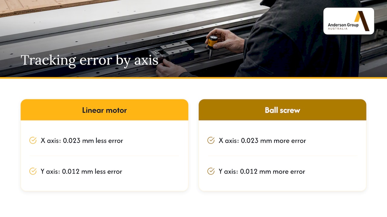
Linear motors can cut dynamic tracking error measurably on adaptive toolpaths: one euspen comparison recorded 0.023 mm less error on one axis and 0.012 mm on the other versus a ball-screw machine under the same test conditions. That level of tracking improvement matters most on trochoidal or adaptive milling strategies where the tool is constantly changing direction and speed.
The trade-off is damping. Ball screws and their bearings provide passive mechanical damping that a direct-drive axis does not have, so a linear motor’s higher bandwidth has to be matched with enough structural stiffness and control tuning to avoid instability. Well-specified machines handle this through frame stiffness and high-resolution feedback rather than by sacrificing speed.
Managing thermal drift in linear motor feed axes
Coil heating is the dominant thermal source in a linear motor axis, and it behaves differently from the heat a ball screw generates through friction at the nut and bearings: it is concentrated at the primary, moves with the carriage on moving-coil designs, and scales with duty cycle rather than travel distance. Left unmanaged, that heat couples into the machine structure and shows up as geometric error at the tool tip.
Hardware mitigations include liquid or forced-air cooling circuits built into the primary, thermal breaks between the motor and the structural frame, and sensor placement close to the heat source rather than on the machine bed alone. On the modelling side, transient refined heat-generation models that account for varying feed speed and duty cycle reduce temperature-deviation error by 9.6% to 21.2%, and thermal deformation deviation by up to 58.6%, compared with static models. More recent work applies physics-informed neural networks combined with multi-sensor fusion to compensate thermal drift in real time rather than relying on a fixed look-up table.
Verification should include a dedicated thermal soak test, running representative duty cycles while logging axis position drift, to confirm the compensation model holds across the machine’s real operating range.
Matching linear motors to the right CNC application
Linear motors earn their keep on nesting and panel-processing lines, high-speed 5-axis work and aerospace mould machining, anywhere rapid point-to-point moves and tight dynamic tracking drive cycle time and surface finish. They are a poor fit for low-cost single-purpose machines or heavy roughing and grinding operations where mechanical damping and low cost matter more than settling time.
A procurement checklist for a linear-motor axis should cover:
- Required encoder resolution for the target positioning accuracy.
- Acceptable settling time for the part geometry and cycle-time target.
- Cooling provision matched to expected duty cycle.
- Enclosure and ingress protection against swarf, particularly in metalworking cells.
- A maintenance plan covering magnet-track cleaning and scale protection.
- Acceptance-test metrics agreed with the supplier before sign-off.
Pro tip: Before retrofitting a ball-screw axis with a linear motor, check the existing guideway’s stiffness and the available envelope for the magnet track; the mechanical interface rarely transfers across unchanged.
For panel-processing and nesting work specifically, our Genesis PLUS nesting CNC machine and the GS Series nesting cells are worth comparing against a retrofit on specification and total footprint.
Safety standards and functional-safety integration
Specifying a linear-motor axis means specifying its safety functions alongside its dynamics. AS/NZS 4024.1503:2026 is the current Australian standard covering safety-related parts of control systems, and it carries through the principles of ISO 13849-1 and IEC 60204-1 into local machinery practice. For Power Drive Systems, that means Safe Torque Off (STO) as the baseline safety function, wired into the machine’s emergency-stop and guarding circuits rather than bolted on afterwards.
At commissioning, verify STO response under load, confirm emergency-stop category matches the risk assessment, and document the test. Our practical checklist for AS/NZS 4024 compliance and MGT Italia’s safety standards guide are useful references when building out the safety file.
Anderson Group Australia: where linear-motor expertise fits our range
We supply CNC machinery, servicing and parts to Australian manufacturers, with a primary focus on the kitchen, cabinet, joinery and furniture sector. When nesting and panel-processing customers ask about direct-drive dynamics, we talk through the trade-offs against our Genesis PLUS and GS Series nesting platforms, matched to the panel sizes and cycle times the job actually needs.
For large non-ferrous-metal and composite workpieces, the Anderson MASS-5 large-scale 5-axis machining centre is a separate range from Focaseiki machining centres. Confirm the axis-drive configuration against the actual application.
- We advise on machine selection and specification, not subcontract cutting or machining.
- We support commissioning conversations around encoder resolution, cooling and safety interfaces.
- We supply parts and servicing after the sale, for the machine’s working life.
Talk to us before you commit to a feed-drive spec
If you are weighing a linear-motor retrofit or a new nesting cell against the numbers in this article, we can talk through what actually fits your panel sizes, cycle-time targets and shop floor. We lead with woodworking and nesting machinery because that is where most of our customers sit, and our Genesis PLUS and Wood Machinery range cover panel processing from entry-level nesting through to high-throughput cells.

For metal and aluminium work, our Metal Machinery range and the Focaseiki production and vertical machining centres cover the equivalent ground. Wherever your job sits, we work from the verified specification on each product page rather than a generic claim, so get in touch to talk through your application and request a quote.
FAQ
What is the main advantage of a linear motor over a ball screw in CNC?
Linear motors remove the screw and nut interface entirely, which eliminates backlash and typically settles in under 15 milliseconds compared with 30 to 80 milliseconds for a ball screw. That speed advantage is most valuable on nesting and panel-processing work with frequent short moves.
How do linear motors cause thermal error and how is it managed?
Coil heating at the primary is the dominant thermal source, and it couples into the machine structure as geometric error if left unmanaged. Cooling circuits, thermal breaks and transient thermal models, including physics-informed neural network approaches, are used to compensate drift in real time.
Do linear motors need special safety provisions compared with other drives?
Linear motors integrate into the same Power Drive System safety framework as other servo axes, requiring functions such as Safe Torque Off under AS/NZS 4024.1503:2026. Commissioning should verify STO response and emergency-stop integration before production use.
Are linear motors suitable for metalworking as well as woodworking machines?
Yes, though exposed permanent magnets can attract metallic swarf, which is why some metalworking machine builders choose reluctance or iron-core alternatives to reduce that issue. Enclosure design and a regular cleaning schedule for the magnet track address the same problem in machines that do use permanent magnets.
Can an existing ball-screw CNC axis be retrofitted with a linear motor?
A retrofit is possible but depends on the existing guideway’s stiffness and the available envelope for the magnet track, since the mechanical interface rarely carries over unchanged. Checking these factors before committing avoids a costly mismatch between the new motor and the old structure.
Sources
- AS/NZS 4024.1503:2026 (standards store entry)
- Dynamic machining and motion performance in state-of-the-art linear motor and ball screw-based CNC machine tools (euspen)