
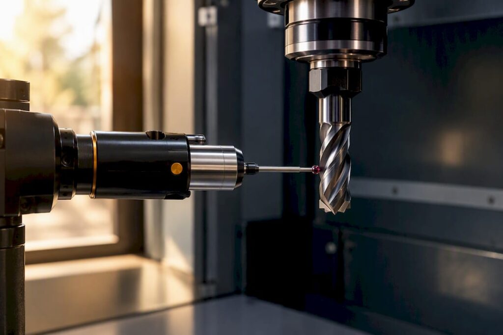
A tool length setter is an on-machine reference device that measures a tool’s Z length quickly and repeatably, so the controller can set accurate offsets without manual test cuts. Production operators running nesting, panel-processing or VMC work gain the most, since every tool change stops costing setup minutes. The sections below cover the hardware types, the probing cycle, installation steps and the rules that keep a tool datum trustworthy.
TL;DR:
- Automated tool setters with high repeatability can maintain Z offset accuracy within 0.2 to 1.5 microns, depending on the model and technology.
- Proper installation requires secure mounting, correct wiring, and precise configuration of the setter height and GoTo position to avoid measurement errors.
- Using a tool setter for frequent tool changes significantly reduces setup time and helps detect broken tools or thermal drift early.
- Linear probes or contact units are best suited for continuous high-volume production, while simpler touch plates work for infrequent use or lower-volume work.
- Never change tools after homing without re-homing or issuing an M06 command to keep the tool datum aligned and prevent offset invalidation.
Table of Contents
- Types of tool length setters and where each one fits
- How automated tool setters actually measure a tool
- Where a tool setter earns its keep on the shop floor
- Installing and configuring a tool setter on your machine
- Protecting the tool datum: rules that prevent scrap
- Diagnosing a failed probe or a wrong offset
- Where operator training and Anderson’s commissioning fit in
- Getting your machine set up with reliable tool setting
- Sources
- FAQ
Types of tool length setters and where each one fits
Most shops choose between a few hardware families, and the right one depends on swarf exposure, mounting space, and how often tools change. A touch plate is the simplest: a flat reference surface the tool jogs down onto, with plate thickness entered manually or measured by a wizard. A contact tool setter is a fixed, spring-loaded probe that trips an input the moment the tool tip contacts it, removing the need to key in plate thickness each time. Radio or infrared probes communicate wirelessly with the controller, useful where cabling to a moving head is impractical.
Renishaw’s LTS and similar contact units are built for shop-floor conditions, with air-blast clearing and sealing against coolant and swarf.
- Touch plates suit lower-volume work and machines without a spare probe input, but need manual thickness entry unless paired with a wizard.
- Contact tool setters offer the best balance of speed and reliability for panel-processing and nesting cells running frequent tool changes.
- Radio/optical probes avoid trailing cables on gantry or moving-column machines but add battery and signal maintenance.
- DIY plates work for occasional use but lack the repeatability data and robustness of a manufactured unit.
How automated tool setters actually measure a tool
An automated cycle follows a fixed sequence, and understanding it helps you diagnose a bad reading instead of just re-running the probe and hoping. The controller moves the tool to a stored GoTo position above the setter, then executes:
- Fast approach, moving quickly until the probe input trips or a Search Z travel limit is reached.
- Back-off, retracting a short distance to clear the trigger point.
- Precise touch-off, approaching again at a slow feed rate for an accurate trigger reading.
- Second back-off, clearing the probe stem before any further move.
- Confirmation, where the controller compares the reading against expected tolerances and stores the offset.
Before any of this runs reliably, you need to confirm the correct probe input is selected (probe, probe1 or equivalent, depending on controller) and that jogging the probe by hand toggles the input state on screen. MillMage’s probing guide sets out the key parameters: Search Z (the maximum travel allowed before the cycle errors out), fast and precise feed rates, precise probe distance and backoff distance. Get Search Z wrong and the tool either crashes into the setter or the cycle times out before contact.
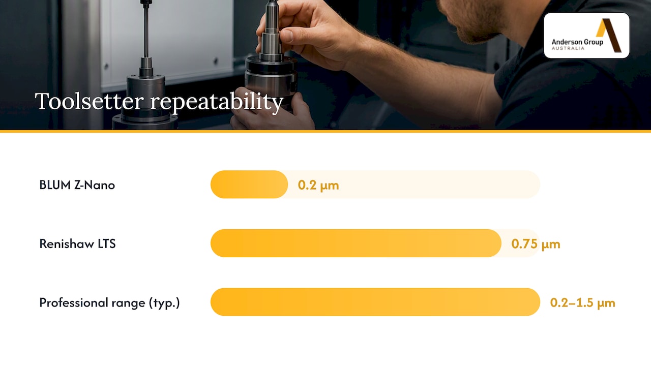
Repeatability determines how tight your final tolerances can be. Renishaw’s LTS is rated at 0.75 micron repeatability, and BLUM’s Z-Nano reaches around 0.2 micron on critical length and diameter settings, with professional units generally sitting between 0.2 and 1.5 micron depending on model and technology. That figure matters because it sets the floor for how consistent your Z offsets can be across a shift, independent of operator skill.
Where a tool setter earns its keep on the shop floor
The most obvious win is initial Z setting: instead of a manual test cut and calliper check on first-off, the setter measures each tool against a common reference in seconds. That same reference lets you recover a program after a crash or power loss without re-zeroing by hand.
- Automated tool changes benefit most, since every new tool in the magazine gets measured against the stored reference automatically.
- Broken-tool detection uses the same probe cycle: a tool measuring shorter than expected flags breakage before it ruins a part.
- Thermal compensation on long runs re-measures tools periodically to catch spindle growth or tool wear before it drifts out of tolerance, a point Renishaw?userLanguage=en&) covers in its broken tool detector documentation.
- High tool-change frequency work, like nested-based panel processing with many router bits, sees the largest proportional time saving.
Pro Tip: Pair a tool setter with controller-based tool-life monitoring so wear trends show up before a tool fails mid-run.
Installing and configuring a tool setter on your machine
Getting the hardware mounted and the controller talking to it correctly is most of the job. Work through it in this order:
- Choose a mounting position, fixed in a permanent corner of the table or random on a T-slot, depending on your fixturing and available travel.
- Secure it mechanically, since a setter that shifts under vibration invalidates every reading taken afterwards.
- Wire the probe to the correct input on the controller and confirm the assignment matches your control’s documentation, whether that is MASSO or another platform.
- Test the trigger manually by pressing the probe stem and watching for the indicator light or on-screen input state to change.
- Enter the setter height, either by direct measurement or by running the controller’s Z-position wizard if one is available.
- Define the GoTo position the machine moves to before each probing cycle, clear of clamps, stock and other fixtures.
- Review soft limits, since an external setter mounted outside the normal working envelope may need travel limits adjusted or temporarily disabled to reach it, then restored afterwards.
Workholding and datum logic on the table itself affects how much clearance you have for a fixed setter, so it is worth reviewing fixture layout at the same time as probe placement. MachPro’s tool setter documentation covers equivalent setup steps for that control platform, including probe input selection and trigger testing.
Protecting the tool datum: rules that prevent scrap
The single rule that causes the most damage when ignored: never change the tool in the spindle after homing without issuing an M06 tool-change command or re-homing the machine. MASSO’s documentation is explicit that skipping this step invalidates the stored datum, because the controller still references the offset for the tool it thinks is loaded.
- Keep the reference tool consistent, since every other tool’s offset is calculated relative to it.
- Synchronise the tool library whenever a tool is replaced, reground or swapped for a different length.
- Confirm the spindle is stationary before any probing cycle starts, never probe with the spindle rotating.
- Use the two-stage approach (fast then slow) every time, rather than a single fast touch, to protect the probe stem and improve accuracy.
Re-measure tools after any crash, after extended runs where thermal drift is likely, or when wear is suspected on a specific tool rather than waiting for a scheduled interval.
Pro Tip: Log which tool is your reference tool on the machine itself, not just in the control, so a relief operator does not accidentally swap it out.
Diagnosing a failed probe or a wrong offset
When a tool offset looks wrong, work through checks in this order rather than immediately re-homing the whole machine:
- Confirm the probe input state changes when you press the stem by hand, and check the indicator light responds.
- Re-run the probe cycle and compare two consecutive readings. A significant difference between them points to a mechanical or wiring fault, not a one-off glitch.
- Verify Search Z covers the full travel to the setter position, since a value set too short will fault the cycle before contact.
- Inspect the probe stem and tip for swarf, coolant residue, or physical damage, and check the mounting is still rigid.
- If the datum is suspect, re-home the machine, re-measure the reference tool first, then re-enter the setter height before trusting any further readings.
Where operator training and Anderson’s commissioning fit in
Reliable tool setting depends as much on procedure as on hardware. The national training unit FWPCOT3289 outlines the skills expected of a competent operator: setting tool datums correctly, entering tooling offsets, running trial cuts and verifying first-off samples before full production.
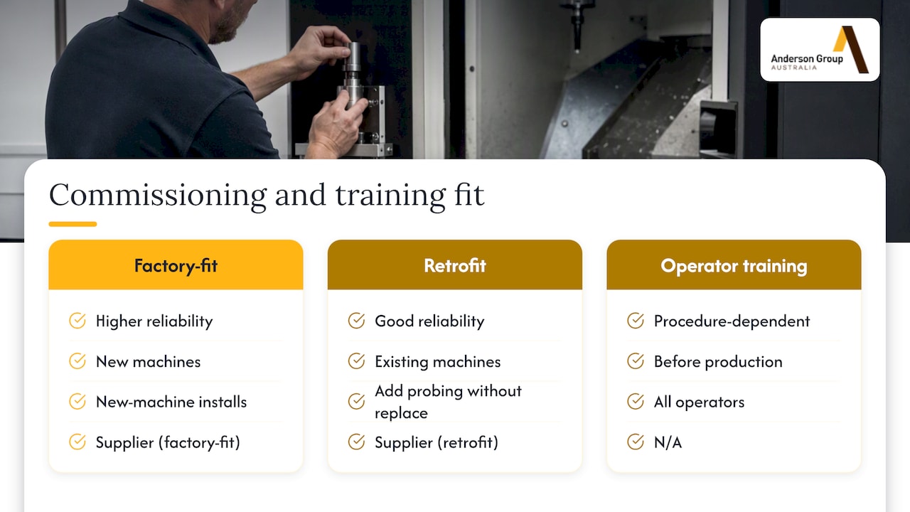
A supplier of CNC machinery for wood, metal and advanced materials manufacturing can commission probing systems as part of new machine installs or as a retrofit on existing equipment. A factory-fit setter is usually the more reliable option on a new machine, while a retrofit suits shops adding probing to an existing cell without replacing it. Anderson’s guidance on factory-fit and retrofit probing commissioning covers what that process involves for panel-processing and nesting equipment.
Getting your machine set up with reliable tool setting
Choosing the right tool setter only matters if it is mounted, wired and configured correctly from day one, and that is where a lot of shops lose the time a setter is supposed to save. Anderson Group Australia supplies CNC machinery across wood, metal and advanced materials, and can commission probing systems as part of a new machine purchase or as a retrofit on equipment already on your floor.

For joinery, cabinet and furniture shops running nested-based panel work, the Genesis PLUS nesting CNC machine and the broader Wood Machinery range are built around the tool-change frequency that makes a setter worthwhile. Metal and aluminium manufacturers running VMC or production machining centres can review the Metal Machinery range for equivalent Focaseiki options.
- Anderson supplies machinery, servicing and parts, and does not offer subcontract cutting or machining.
- Product specifications are verified against each machine’s own product page before you buy.
- Commissioning covers both new installs and retrofits to existing machines.
If you are weighing up a new machine or adding probing to an existing one, get in touch to discuss your application or request a quote.
Sources
- MASSO — How tool setter works / Auto Tool Zero
- MillMage tool length probing guide
- FWPCOT3289 Load and prove operating program for CNC machine
FAQ
What does a tool setter do?
A tool setter measures a tool’s length against a fixed reference point on the machine, storing that measurement as an offset the controller uses for every subsequent cut. It detects broken tools by flagging a tool that measures shorter than expected, and supports thermal compensation on long production runs, as described in Renishaw’s tool setter documentation.
Is CNC difficult to learn?
CNC operation has a learning curve, but it is a structured one built around recognised skills such as setting tool datums, entering offsets and verifying first-off parts, which are exactly the competencies covered in national training units like FWPCOT3289. Most operators build competence through a mix of formal training and supervised shop-floor practice rather than trial and error alone.
What is the easiest CNC software for beginners?
There is no single easiest option, since ease of use depends on the controller already fitted to your machine and the complexity of the parts you are running. Platforms like MASSO are documented with plain step-by-step setup guides for functions such as tool setting, which can shorten the learning curve for new operators on that control.
What is tool length compensation in CNC?
Tool length compensation is the offset the controller applies to account for the difference in length between tools, so the same program moves the tip of each tool to the correct Z position regardless of which one is loaded. This offset is typically generated by a tool length setter probing cycle rather than manual measurement, as outlined in MillMage’s probing guide.