
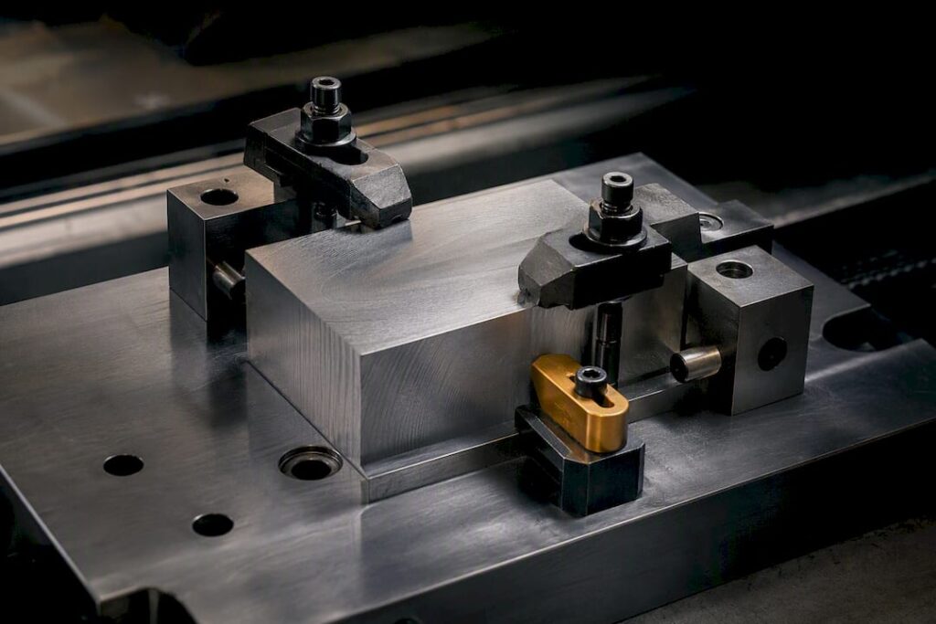
Vise setups with soft jaws, step and toe clamps, fixture plates, vacuum and magnetic chucks, and modular or dedicated fixtures cover almost every job you’ll face on a CNC machine. Which one wins comes down to a simple equation: part geometry, material, batch size, and tolerance dictate the method, not personal preference or whatever fixture is closest to the machine. Get that match right and everything downstream, from datum strategy to clamping force to fixture verification, falls into place.
TL;DR:
- Matching fixture method to part geometry, material, and batch size is critical; a poor fit causes chatter, dimensional drift, and scrap.
- Soft jaws and custom nests improve repeatability for irregular shapes, but require upfront setup and are limited to specific part families.
- Proper datum strategy and the 3-2-1 locating principle ensure accurate part positioning, avoiding over- or under-constraining, which leads to inaccuracies.
- Consistent probing before cutting, including fixture verification and offset checks, is the most effective way to prevent costly errors.
- Regular maintenance and safety checks on workholding devices are essential, as damage or misalignment degrade accuracy and pose safety risks.
Table of Contents
- What are the main CNC workholding methods and when do you use them?
- Datum strategy and the 3-2-1 locating principle
- Vise setup and soft jaws: getting repeatable seating
- Clamping force versus part distortion
- Supporting thin, weak or irregular parts
- Fixture clearance and tool access
- Modular versus dedicated fixtures for production runs
- Second-operation fixturing and probing for fixture verification
- How to choose the right workholding method for the job
- Pre-run fixturing checklist and verification
- Who’s behind this guide
- Why secure workholding actually matters
- Maintenance and care of workholding devices
- Safety best practices for CNC workholding
- Alignment and calibration techniques for fixtures
- Material-specific workholding considerations
- The gap between textbook fixturing and shop-floor reality
- Where Anderson fits into your workholding decisions
- Sources
What are the main CNC workholding methods and when do you use them?
Every job starts with the same question: what’s actually going to hold this part still while a cutter tries to move it? Poor fixturing shows up as chatter, dimensional drift, broken tools, and scrap. It isn’t a footnote to the machining process, it’s a core part of process engineering in its own right. Here’s how the common methods stack up.
Vises remain the default for general machining. They’re fast to set, cheap to buy, and forgiving on rectangular or roughly prismatic stock. A standard vise struggles the moment your part has curves, thin walls, or a shape that doesn’t sit flat against hardened steel jaws.
Soft jaws solve that problem. Machined from aluminium or mild steel to match a specific part’s profile, they let a vise grip irregular shapes with far more contact area and far less risk of marking a finished surface. They cost setup time up front (you’re cutting a custom jaw before you cut the actual part) but pay that back many times over on repeat jobs, since every part seats identically.
Step and toe clamps, along with T-slot hold-downs, are the workhorses for plate work and oversized parts that won’t fit a vise. They clamp from above rather than from the side, which matters when you need the sides of a part clear for machining. The trade-off is setup time and the constant risk that a clamp sits inside the tool’s path.
Fixture plates and tooling plates give you a flat, pre-drilled or grid-tapped base to build repeatable setups on. Once you’ve located a part relative to the plate’s grid once, every future setup on that plate references the same coordinate system. This is where batch production starts to pay off.
Vacuum and magnetic chucks solve a different problem entirely: thin, flat, or delicate parts that would distort under mechanical clamping. Vacuum works on non-porous materials of almost any composition; magnetic chucks work only on ferrous metals. Neither is a universal answer. Vacuum and magnetic systems rarely replace mechanical fixtures for irregular geometry or high cutting-force operations, where the holding force simply can’t compete with a mechanical clamp.
Modular fixturing systems, built from precision base plates, towers, and reconfigurable clamps, sit between manual setups and fully dedicated fixtures. They’re the pragmatic choice for medium production runs where a one-off jig is overkill but a custom fixture doesn’t justify its own tooling budget.
Custom nests and specialised jigs earn their keep on genuinely irregular geometries: castings, forgings, organic shapes, anything a standard vise or plate simply can’t locate reliably. They cost more to design but they’re the only real option once a part’s geometry rules out everything else on this list.
Datum strategy and the 3-2-1 locating principle
Locating comes before support, and support comes before clamping. Get that order wrong and no amount of clamp force will fix a part that was never positioned correctly in the first place.
A datum is a reference surface, line, or point you use to define a part’s position and orientation. Every dimension on a drawing traces back to one, and your fixture’s job is to physically recreate those same references on the machine table. Fixture design always follows the same sequence: locate the part, support it against deflection, then clamp it to hold that position through the cut.
The 3-2-1 principle is how you do the locating. A rigid body has six degrees of freedom: three translations along the X, Y, and Z axes, and three rotations around them. Three points on a primary datum surface remove three degrees of freedom (the two rotations and one translation tied to that plane). Two points on a secondary surface remove two more. One point on a tertiary surface removes the last one. Six points, six degrees of freedom, fully located.
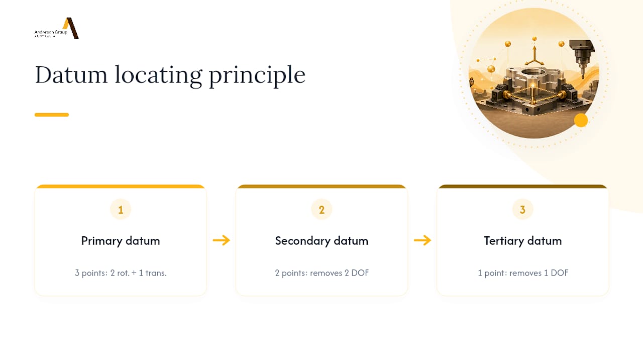
For a prismatic block, this looks straightforward: three supports under the bottom face, two against one side, one against the end. Round parts locate differently, typically against a chuck or V-block that constrains the diameter and a face stop that constrains length. Irregular castings often need custom-machined locating pins that match specific as-cast features, since there’s no clean flat surface to reference.
Over-constraining is the mistake that catches out even experienced machinists: adding a seventh or eighth contact point “for extra security” actually fights the other locators, rocking the part or inducing stress that releases as distortion once you unclamp. Under-constraining is more obvious. A part that can rock or shift under cutting load is a part that’s going to produce inconsistent dimensions from the first hole to the last.
Vise setup and soft jaws: getting repeatable seating
A vise that looks tightened correctly can still be wrong in ways that don’t show up until you’re measuring the finished part. The seat is where problems start. Any grit, chip, or burr trapped between the part and the jaw or the vise base lifts the part by fractions of a millimetre, which is more than enough to blow a tight tolerance. Check the datum surfaces and the vise bed every single time, not just on the first part of a run.
Jaw contact matters as much as jaw pressure. A standard vise makes line contact along the top and bottom edges of serrated jaws, which is fine for rough stock but leaves marks and inconsistent grip on finished surfaces. This is exactly the gap soft jaws close.
Machine soft jaws directly in the vise they’ll be used in, cutting the profile with the jaws clamped at the same pressure they’ll hold during production. This “in situ” machining accounts for any slight deflection in the vise body itself, so the jaw profile matches the real clamping geometry rather than a theoretical one. Aluminium is the standard soft jaw material for most work since it’s fast to machine and gentle on finished parts; mild steel earns its place when you need more rigidity for heavier cuts or harder stock.
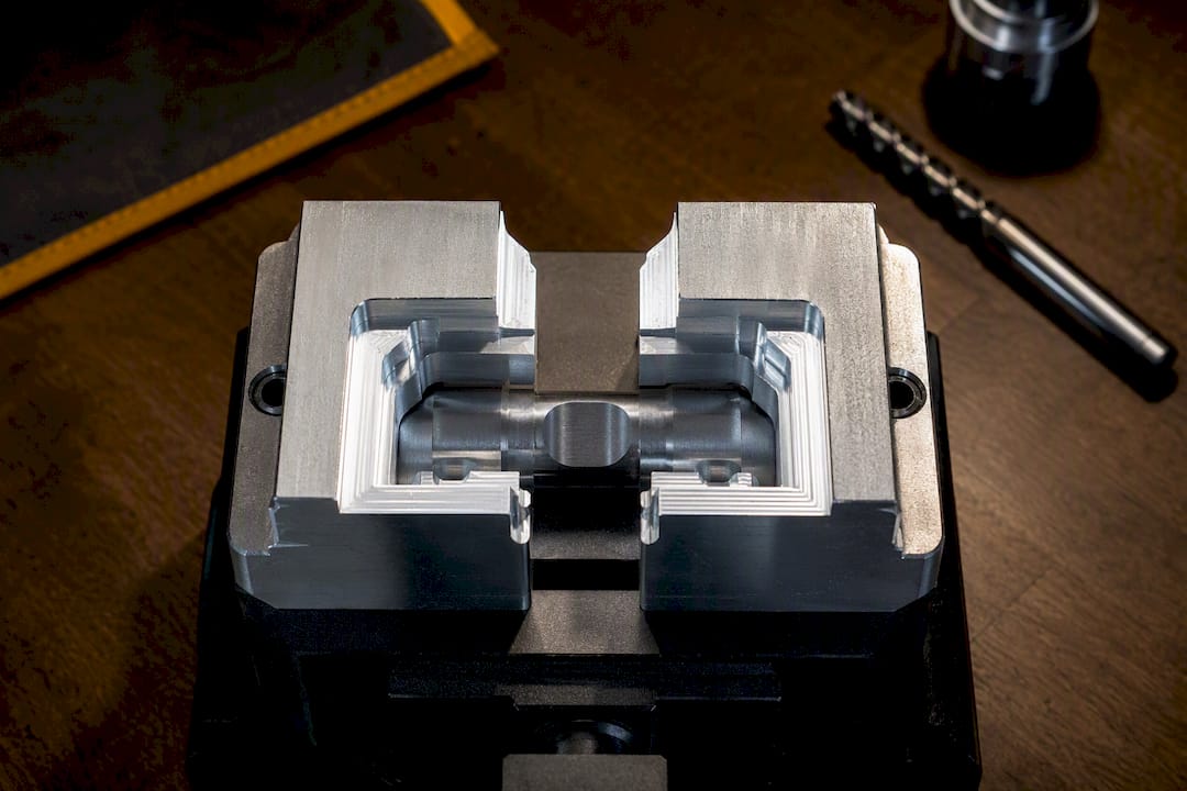
The payoff is real: once a soft jaw is cut to a part’s profile, every subsequent part in that run seats identically, with a fraction of the manual alignment time a standard vise setup demands. The limit is equally real. Soft jaws are a per-part-family tool. Change the geometry significantly and you’re cutting new jaws, which only makes economic sense past a certain batch size.
Clamping force versus part distortion
Clamp force exists to counter the cutting force trying to lift, push, or rotate the part during machining. Set it too low and the part shifts mid-cut, ruining the job and possibly the tool. Set it too high, particularly on thin sections, and you get a different failure mode: the part deforms elastically under the clamp, gets machined in that deformed state, then springs back to a slightly different shape the moment you release it.
Strategic fixture design has to balance both failure modes at once: enough rigidity to resist cutting forces, but not so much clamp pressure concentrated at a single point that thin sections distort. This is the single most common cause of “the part measured fine on the machine but failed inspection an hour later.”
Pro Tip: If a thin-walled part fails inspection consistently in the same spot, check your clamp points before you check your program. Spring-back from a single over-tightened clamp almost always shows up as a localised dimensional error, not a random one.
For thin-walled parts, distribute clamping load across multiple lower-pressure points rather than one high-pressure point. A wide, flat clamp pad spreads force over more surface area than a narrow toe clamp tip. As a working check, if you can visibly see or feel a part flex under hand pressure at the clamp location, it’s going to distort under machine clamping too. That’s your cue to add support underneath before you clamp, not after.
Where consistency matters more than one-off convenience, hydraulic or pneumatic clamping earns its cost. Powered clamping systems deliver the same force every single time, removing the variability that comes from one operator’s wrench torque differing from another’s across a production run.
Supporting thin, weak or irregular parts
Thin plates, delicate castings, and parts with unsupported spans all share the same failure risk: sagging, spring-back, or vibration under cutting load, even when the clamping itself is correctly set.
Rest pads and step supports fill the gap under a part’s unsupported sections, converting what would be a suspended span into a fully backed surface. Backup screws work the same way but adjustable, which matters when part thickness varies slightly between castings or when you’re supporting an irregular underside that a fixed pad can’t match. Machinable filler blocks go a step further: you pour or fit a sacrificial material into the gap, machine it flush to match the part’s contour, then use that custom-fitted block as a support for the actual production cut.
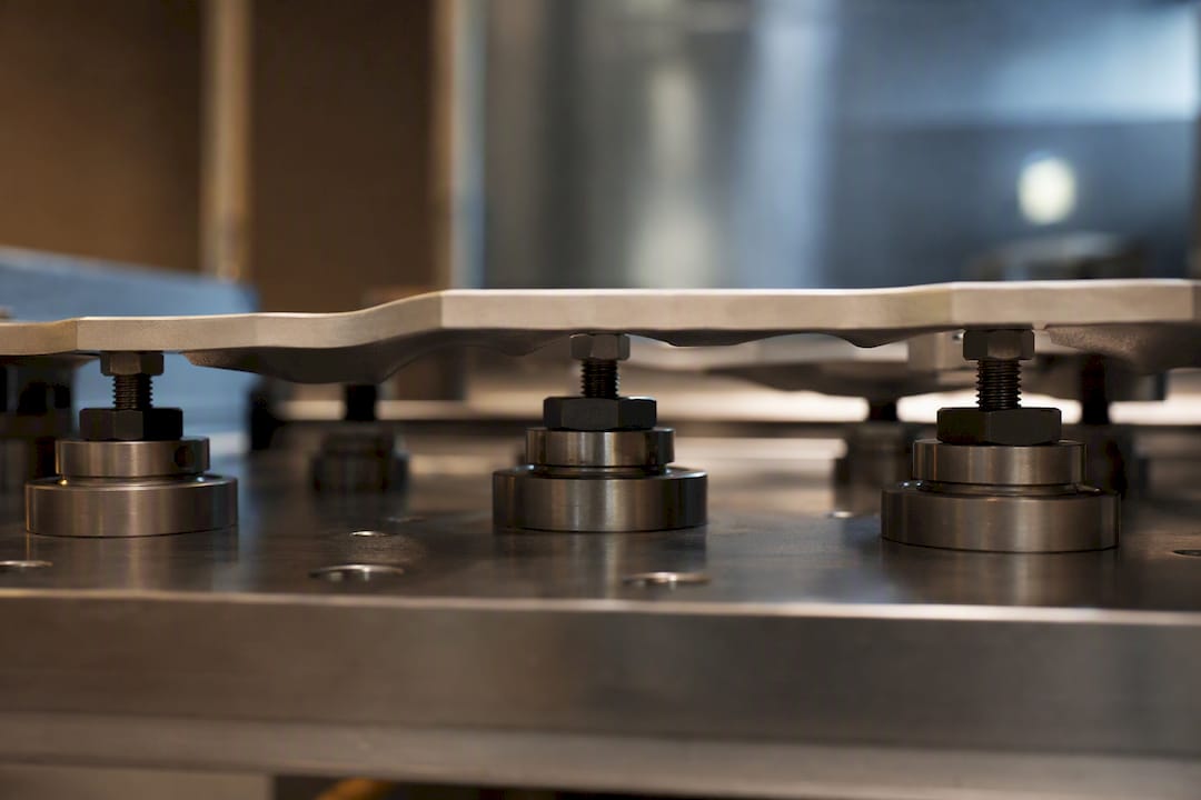
Custom nests and soft-jaw pockets earn their place on genuinely delicate shapes, thin composite panels, cast housings with irregular backs, anything where a flat rest pad simply can’t follow the geometry. The nest holds the part’s full underside rather than a handful of points.
None of this works if it’s an afterthought bolted on after the toolpath is programmed. Plan support locations into the CAM program from the start, so the cutter never passes over a genuinely unsupported span at full engagement. A support added after the fact often ends up in the tool’s path, which just trades one problem for another.
Fixture clearance and tool access
A fixture that holds a part perfectly but blocks the cutter is a fixture that needs to be redesigned. The most common collision mistake is a clamp positioned exactly where an end mill needs to travel, discovered mid-cycle rather than at the design stage. Probe collisions and tool-change clearance issues follow close behind, especially on parts where the fixture sits close to the spindle’s full travel.
Risers, tombstones, and elevated fixture bases solve two problems at once: they lift the part clear of clamps and locators sitting on the table, and they can bring the part into a machine’s optimal rigidity zone relative to the spindle. For multi-face and 5-axis work, fixture clearance also has to account for rotating axes, keeping the part and its clamps well clear of the swing radius through every programmed orientation.
Compact clamp designs help here. Toe clamps and swing clamps sit lower and narrower than a traditional strap clamp, giving the cutter more usable space around the part. Chamfering fixture edges and clamp bodies removes another common snag point on multi-axis jobs where the tool approaches from angles a simple vertical setup never has to consider.
Before the first cut, check the actual reach: spindle-to-part clearance, tool holder length, and the fixture’s tallest feature all need to clear each other through the full range of motion the program calls for, not just the starting position.
Modular versus dedicated fixtures for production runs
Modular fixturing systems use standardised, reconfigurable components: precision base plates, adjustable towers, and interchangeable clamps that bolt into a repeating grid. Dedicated fixtures are the opposite, purpose-built, often one-piece machined tooling designed around a single part’s exact geometry.
The trade-off runs in predictable directions. Dedicated fixtures win on rigidity and setup speed once built, since every locating and clamping feature is already exactly where the part needs it. Modular systems win on flexibility and upfront cost, but typically deliver less rigidity than a purpose-built equivalent, and setup takes longer since an operator is assembling and aligning components rather than just dropping a part into a pre-built jig.
Volume is what decides between them. A one-off or prototype job rarely justifies a dedicated fixture at all, use a vise, soft jaws, or a simple modular setup and move on. Modular fixturing tends to make the most economic sense in the 5 to 50 part range, where the flexibility to reconfigure outweighs the rigidity advantage of dedicated tooling. Past roughly 50 parts, particularly on jobs with tight tolerances or difficult access, the setup-time savings of a dedicated fixture usually justify its upfront tooling cost.
If you’re not ready to commit to a full dedicated build, standardising your modular components across jobs, same base plate grid, same clamp family, still gets you most of the repeatability benefit without locking in a single-part-specific fixture. It’s a middle path worth taking seriously before jumping straight to custom tooling.
Second-operation fixturing and probing for fixture verification
Once you flip a part for a second operation, the datums you located against in operation one are often gone, machined away, or now inaccessible. This is where a lot of setups quietly lose accuracy: the fixture for op two references whatever surface is convenient, not whatever surface is actually reliable.
The fix is to build op two around features you created deliberately in op one specifically for this purpose. Machined bores, finished faces, and dowel pins matched to the op-one geometry give the second fixture a clean, known reference rather than an approximate one.
A short verification routine before cutting catches problems early:
- Probe the part’s seated position against the fixture’s known datum before the first cut, not after.
- Check soft jaw or nest contact against the finished surfaces from op one.
- Confirm G54 through G59 offsets are calling the correct coordinate system for this specific fixture, not a leftover from the previous job.
- Re-verify offsets between rough and finish passes if the part was unclamped or repositioned between them.
Probing here isn’t a formality. Verifying datum position and seating with a probe cycle before the first part catches a misaligned fixture in seconds rather than after a scrapped part tells you something was wrong.
How to choose the right workholding method for the job
Match the method to the job using a short set of practical questions rather than habit or whatever’s closest to the machine.
- What’s the material? Ferrous metal opens up magnetic chucking as an option; non-ferrous metals, plastics, and composites don’t have that option and lean toward vacuum, mechanical clamping, or soft jaws instead.
- What’s the part geometry? Flat and thin favours vacuum or magnetic; prismatic and rigid favours a vise; irregular or organic shapes point toward custom nests or dedicated fixtures.
- What’s the tolerance? Tight tolerances on repeat parts justify the time cost of soft jaws or a dedicated fixture; loose tolerances on a one-off don’t.
- What’s the batch size? One-off jobs rarely justify anything beyond a vise or simple modular setup; medium runs favour modular fixturing; high volume justifies dedicated tooling.
- What are the expected cutting forces? Heavy roughing passes need mechanical clamping with real holding force; light finishing passes on delicate stock can often get away with vacuum.
- Is the part accessible from all required angles? If not, the fixture needs redesigning before the program does, not after.
Pro Tip: When in doubt between two methods, build the fixture for the harder operation in the job, usually the heaviest roughing pass, not the easiest one. A fixture that survives your worst cut survives everything gentler than it.
Red flags worth stopping for: a clamp you can see interfering with the toolpath on screen, a part that flexes visibly under hand pressure at the clamp point, or a fixture design that only works if every dimension on the part is exactly nominal. Any of those is worth a second look, and a genuinely unusual geometry or a high-value production run is often worth a conversation with a fixturing specialist or your machine vendor before you cut metal.
Pre-run fixturing checklist and verification
Run this before the first cut on any new setup, not just the tricky ones.
- Part seats flat against every datum surface, with no rock or gap.
- No chips, grit, or burrs trapped under datum faces or jaw contact points.
- Jaw or clamp grip is firm but not deforming the part visibly.
- Clamp force is distributed appropriately for thin or delicate sections.
- Critical unsupported surfaces have rest pads, filler blocks, or backup screws in place.
- Tool path clears every clamp, locator, and fixture edge through the full program.
- Offsets (G54 to G59) are verified against the correct fixture, ideally by probe.
- Fixture clearance checked for the tallest tool holder and longest reach in the program.
Record the finished setup, clamp torque, jaw material, offset values, fixture photo, in a setup sheet tied to that specific job number. The next operator running the same part shouldn’t have to rediscover any of this from scratch.
| Checklist stage | What to verify | Why it matters |
|---|---|---|
| Seating | Part sits flat, no trapped debris | Prevents datum offset errors |
| Clamping | Grip firm, no visible distortion | Avoids spring-back after release |
| Support | Critical spans backed | Stops sagging or vibration |
| Clearance | Tool path clear of fixture | Prevents crashes |
| Verification | Offsets probed and confirmed | Catches misalignment before the cut |
First-part inspection should check every critical dimension against the drawing before the run continues, with sign-off recorded against that specific fixture setup. If the first part passes, the fixture is proven for that job; if it doesn’t, you’ve caught the problem before it became ten scrapped parts instead of one.
Who’s behind this guide
This guide draws on published fixturing resources from Scott, whose writing for Anderson covers vacuum fixturing and zero-point systems in more technical depth than a single overview article can manage. The vacuum fixturing guide covers when vacuum genuinely works and when it doesn’t; the zero-point fixturing guide covers pallet interfaces and setup time reduction for shops running repeat jobs.
Anderson Group Australia has built CNC machinery for woodworking, metalworking, and advanced materials since 1972, which means the practical tips in this guide come from decades of watching what actually goes wrong on real production floors, not just what’s theoretically correct on paper. The checklist items, clamp force cautions, and datum strategy above reflect that accumulated shop-floor experience as much as engineering principle.
Why secure workholding actually matters
Every failure mode in CNC machining traces back, eventually, to something moving that shouldn’t have. Chatter, the harsh vibration that leaves a rippled surface finish, is very often a workholding problem disguised as a tooling problem. A part that isn’t rigidly located will resonate under cutting load no matter how good your feeds and speeds are.
Dimensional drift is the quieter version of the same failure. A part that shifts by a few microns mid-cut, whether from insufficient clamp force or a chip trapped under a datum surface, produces a part that measures wrong in ways that don’t show up until final inspection. By then the material, the machine time, and the tooling wear are all sunk costs.
Broken tools follow naturally from either problem. A cutter engaging a part that’s moving unpredictably sees load spikes it was never programmed for, and carbide doesn’t forgive that kind of surprise. Scrap is the final, most expensive symptom, the point where a workholding problem stops being an inconvenience and starts being a cost with a dollar figure attached.
None of this is exotic engineering. It’s the reason locating comes before support, support comes before clamping, and verification comes before the first cut on every job, not just the difficult ones.
Maintenance and care of workholding devices
A vise that’s been dropped, a fixture plate with a burred T-slot, a soft jaw with a chip embedded in its face, all of these degrade accuracy long before they degrade obviously enough for anyone to notice by eye.
Clean fixture surfaces and datum faces after every job, not just when they look dirty. Coolant residue and fine chips build up in ways that are barely visible but still enough to lift a part by the fraction of a millimetre that matters on a tight tolerance.
Check vise jaws and soft jaws periodically for wear, deformation, or embedded debris that a quick wipe won’t remove. A jaw face that’s taken repeated impacts or heavy clamping loads over hundreds of cycles can develop subtle high spots that throw off seating accuracy on later parts.
Inspect T-slots, dowel pins, and locating bushings for wear, since these are the features that carry positional accuracy from one setup to the next. A worn dowel pin with play in its bore reintroduces exactly the kind of positional uncertainty the 3-2-1 principle was supposed to eliminate.
Store modular fixture components in a way that protects locating surfaces from knocks and corrosion between jobs. A base plate or tower that’s been sitting in a drawer picking up surface rust is not the same precision reference it was when it was new, and using it without checking invites problems you won’t see until inspection.
Safety best practices for CNC workholding
Clamp force strong enough to hold a part against cutting loads is also strong enough to injure someone if it releases unexpectedly or if fingers are anywhere near a closing clamp.
Never reach into a fixture area while the machine is cycling, even for a quick visual check. Confirm clamps and vises are fully seated and torqued before closing the enclosure door, and never rely on a part “feeling secure” by hand as a substitute for checking actual clamp engagement.
Loose or damaged fixture components, a cracked soft jaw, a worn T-nut, a hydraulic clamp with a slow leak, are safety issues before they’re accuracy issues. A clamp that loses force mid-cycle can send a part flying at spindle speed, and that risk exists whether the part is worth $5 or $5,000.
Hydraulic and pneumatic clamping systems need their own safety checks: verify line pressure is within the fixture’s rated range before running, and never bypass a pressure interlock to speed up a setup. These systems exist specifically to give consistent clamp force, and disabling a safety interlock defeats that purpose in the worst possible way.
Keep hands, tools, and loose clothing clear of any fixture with moving locators, swing clamps, or pneumatic actuators, since these can cycle unexpectedly if a control signal arrives while someone’s hands are near the mechanism. Treat every workholding device as if it could move without warning, because on a networked CNC system, it sometimes can.
Alignment and calibration techniques for fixtures
A fixture that was accurate when it was built doesn’t stay accurate forever. Wear, thermal expansion, and accumulated knocks all shift alignment over time in ways that a visual check won’t catch.
Dial indicators remain the simplest calibration tool for checking a fixture’s squareness and flatness against the machine table before a critical job. Sweeping a fixture plate’s surface with an indicator takes a few minutes and catches warping or mounting errors that would otherwise show up as a dimensional error on every part in the run.
Probing cycles built into the CNC control take this further, automatically checking fixture position, part seating, and offset accuracy at the start of a cycle rather than relying on an operator’s manual check. This matters most on multi-part or multi-day runs, where a fixture’s actual position needs confirming every time, not just on day one.
Periodic recalibration matters most for fixtures used across multiple jobs or multiple machines, since a fixture that’s accurate on one machine’s table isn’t guaranteed to be equally accurate on another without re-checking its reference surfaces against that specific machine.
Document the calibration result, not just the fact that a check happened, so a fixture drifting slowly out of tolerance over months of use gets caught by comparing today’s numbers against last month’s, rather than relying on memory.
Material-specific workholding considerations
Metals and plastics behave differently under a clamp, and treating them the same is one of the more common ways a good fixture design goes wrong.
Metals, particularly aluminium and steel, tolerate higher clamp forces without permanent deformation, which is why standard vise and mechanical clamping methods work well for the majority of metal machining jobs. Ferrous metals also open up magnetic chucking as an option that simply doesn’t exist for aluminium, plastics, or composites.
Plastics and composites are a different story. They’re generally softer, more prone to creep under sustained clamp pressure, and more sensitive to localised stress than metals of comparable thickness. A clamp force that’s perfectly safe on a steel bracket can leave a permanent dent or cause long-term dimensional creep on an equivalent plastic part.
Thin-walled plastic and composite parts benefit disproportionately from vacuum workholding, since it distributes holding force across the entire contacted surface rather than concentrating it at a handful of clamp points. This is exactly the use case vacuum chucking was designed for.
Heat matters more for plastics too. Cutting forces and friction generate heat that a metal part shrugs off but that can soften or distort a plastic part mid-cut, especially if it’s already under clamp stress. Lower cutting speeds, sharper tooling, and lighter clamp pressure all help manage this, alongside choosing a support strategy that doesn’t concentrate stress on a material that’s already working harder to hold its shape than steel would.
The gap between textbook fixturing and shop-floor reality
Most fixturing advice treats workholding as a checklist of clamp types. It isn’t. It’s a chain of decisions, locate, support, clamp, verify, and the chain is only as strong as its weakest link. A perfectly executed vise setup means nothing if the part was located against the wrong datum in the first place.
The conventional wisdom oversells dedicated fixtures and undersells discipline. A shop with a mediocre modular setup and a genuine habit of checking for chips under datum faces will out-produce a shop with an expensive dedicated fixture and a casual attitude toward verification. Precision comes from consistency, not from the fixture’s price tag.
If there’s one thing worth prioritising above everything else in this guide, it’s probing before cutting. A thirty-second probe cycle catches the seating error, the misaligned soft jaw, the wrong offset, before it becomes a scrapped part. Everything else, clamp force, support strategy, modular versus dedicated, matters less than that one habit, because it’s the check that catches every other mistake before the spindle starts turning.
— Scott
Where Anderson fits into your workholding decisions
Good workholding only gets you so far without a machine platform rigid and accurate enough to make that fixturing worthwhile. Anderson builds CNC equipment across woodworking, metalworking, and advanced materials, which means fixture and machine decisions get made together rather than as separate problems bolted on after the fact.

For shops weighing modular versus dedicated fixturing on a production job, machine choice matters as much as clamp choice. Anderson’s 5-axis vertical machining centres and production centres with auto pallet changing are built with the clearance and rigidity that multi-axis fixture work demands, so tool access and fixture clearance stop being a fight against the machine’s own limits. Furniture, automotive, aerospace, and general engineering shops running mixed material batches, metals through to plastics and composites, will find equipment purpose-built for exactly the workholding trade-offs covered in this guide, backed by the industries Anderson works with and a company history stretching back to 1972.
If you’re specifying a new machine around a specific fixturing challenge, get in touch with details on your part geometry, material, batch size, and tolerance requirements ready, and request a quote through Anderson’s machinery range to start the conversation.
Sources
- Cnccode
- Fixture design for CNC machining: principles of rigid, repeatable workholding | UTEC resources
- Strategic fixture design for CNC machining centers: engineering principles and best practices – MHFixture
- Introduction to workholding options for CNC machining – Fictiv