
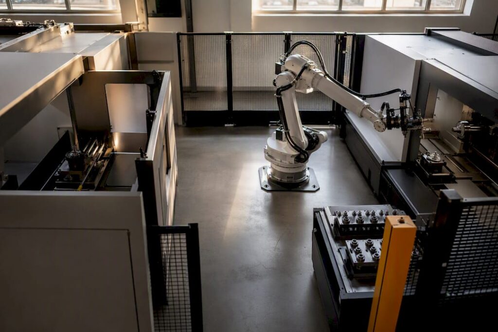
Cellular manufacturing built around one-piece flow beats batch-and-queue for CNC work almost every time it’s applied correctly. Organise machines by part family, balance every station to takt time, right-size your equipment instead of dropping in oversized “monuments,” and match your machine-tending architecture (pallet changer, tombstone, or pallet pool) to your part mix. Get those four levers right and everything else in cell design falls into place.
TL;DR:
- Optimal cellular layouts should keep stations within arm’s reach and standardize work heights to minimize unnecessary travel and cycle times.
- Proper machine-tending architecture must match part volume and complexity, with a focus on fixture flexibility and safety standards.
- Grouping parts into families relies on geometry, routing, demand, and changeover costs, avoiding forced fits for outliers.
- Calculating accurate takt time involves comprehensive work content, including operator travel, inspection, and setup times, with parallel stations for excess workload.
- Using simulation or physical mock-ups before installation helps identify reach and clearance issues, preventing costly reworks and delays.
Table of Contents
- What makes a CNC cell layout actually work?
- How do you design machine tending for robot access and workholding?
- Which cell shape and machine-tending architecture fits your parts?
- How do you group parts into families with PQ analysis?
- How do you calculate takt time and balance the workload?
- How do you right-size machines and fixtures for a cell?
- Should you simulate the layout before installing it?
- Implementation checklist: plan, buy, install, validate, operate
- Practitioner perspective: where experience actually earns its keep
- How Anderson Group Australia supports CNC cell projects
- Sources
- FAQ
What makes a CNC cell layout actually work?
Cellular manufacturing groups dissimilar machines into a compact footprint, usually U-shaped or C-shaped, so one part family moves start to finish without leaving the cell. That’s the whole idea behind one-piece flow: instead of a batch of 500 parts sitting in queue between operations, a single part moves station to station, and lead time can collapse from days to hours.
The mechanism is simple. Batch processing hides problems in inventory. One-piece flow exposes them immediately, because there’s nowhere for a bad part or a stalled station to hide.
A few rules govern whether this actually happens on your floor:
- Keep every station within arm’s reach of the next; every metre of unnecessary travel adds cycle time nobody planned for.
- Set a standard work height across stations so operators (and robot grippers) don’t need constant repositioning.
- Store fixtures, tooling, and raw stock at point of use, not in a central crib three aisles away.
- Run product-quantity (PQ) analysis before you touch a single machine, because it tells you which parts actually belong together.
- Track takt time as the number that governs every station’s target cycle, not just a planning artefact you calculate once and forget.
Skip the PQ analysis and you’ll build a cell that looks efficient on paper and stalls the moment real part variety hits it.
How do you design machine tending for robot access and workholding?
Machine tending fails when planners design the robot in isolation and treat the CNC, workholding, and secondary processes as someone else’s problem. The full cell needs to work as one system: blank feeding, part presentation, machining, deburring, cleaning, and inspection all live inside the cell boundary wherever that’s physically achievable.
Workholding has to be automatable from day one. Vises, chucks, and vacuum tables all work, but each demands a different clearance envelope, and the robot needs to clear tooling reliably on every cycle, not just the test run.
Practical requirements to lock down before you finalise floor position:
- CNC door sequencing and interlocks, checked against relevant ISO robot-cell safety standards before commissioning.
- End-of-arm tooling (EOAT) customised to the part geometry, not a generic gripper forced to fit.
- Safety zoning that accounts for both the robot’s working envelope and an operator’s occasional access for tool changes.
- Secondary processes (chip evacuation, deburr, vision inspection) built into the cell footprint rather than routed to a separate department.
Pro Tip: A second robot is rarely about speed. Add one when a single arm can’t physically service two machines within takt time, not because someone assumes twin robots look more capable on a layout drawing.
Which cell shape and machine-tending architecture fits your parts?
Cell shape and machine-tending architecture are two separate decisions, and conflating them is a common planning mistake.
- U-shaped cells pack the most stations into the smallest footprint and put the operator in the centre with everything in reach. They’re the default choice for one-piece flow but need enough floor depth to swing doors and fixtures.
- L-shaped cells suit sites with an awkward column grid or an existing wall you can’t move. You sacrifice some operator centrality for floor-plan flexibility.
- Straight-line cells work best for long part flows with few branching operations, but they stretch operator walking distance, which eats into takt if you’re not careful.
On the machine-tending side, three architectures cover most robot-tended work. A pallet changer suits one to three part families in a tight footprint. A fixed tombstone with dual side-loading handles higher part counts per fixture. A pallet pool, typically running one or two robots across eight to twenty-four pallets, earns its complexity in high-mix environments where changeover frequency would otherwise kill throughput.
How do you group parts into families with PQ analysis?
Product-quantity analysis starts with a simple matrix: list every part against its volume and routing sequence, then sort for parts that share machine sequence and geometry. Parts that share three or four operations in the same order are candidates for the same cell.
Group by these criteria, in rough order of weight:
- Geometric similarity (size, material, fixturing method).
- Routing similarity through the same machine sequence.
- Volume and demand pattern, since a low-runner mixed into a high-volume family drags down cell balance.
- Changeover cost, because a part needing a completely different fixture might not belong in the cell at all.
If a part’s routing genuinely doesn’t match any family, don’t force it into a cell for the sake of tidiness. A process-focused central line, with parts routed there for that one odd operation, often beats bending a cell’s design around an outlier.
How do you calculate takt time and balance the workload?
Takt time is customer demand divided by available production time, and it sets the pace every station in the cell must hit or beat. It’s a planning number that becomes a physical constraint the moment the line starts running.
Work content calculations need to include everything a station actually does, not just the spindle-on time. That means:
- Operator walking time between stations, which is routinely left out of takt calculations and quietly wrecks the balance once the cell is running.
- Inspection time, whether manual or automated vision, counted against the station performing it.
- Setup and changeover time, amortised across the batch if changeovers happen mid-shift.
When one station’s work content exceeds takt and you can’t trim it further, add a parallel station for that operation rather than letting the whole cell stall behind it. It’s a workable fix, provided the added station doesn’t blow out your footprint or your capital budget.
How do you right-size machines and fixtures for a cell?
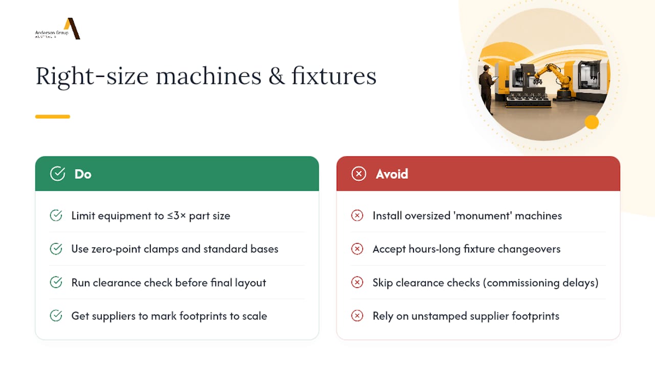
Right-sizing is where most cellular manufacturing conversions go wrong. Planners inherit a large legacy machine, try to fit it into a cell designed for compact flow, and end up with a “monument” that everyone routes work around instead of through. The practical guideline: equipment shouldn’t be more than three times the size of the part it’s producing.
Fixturing matters just as much as the machine itself. Zero-point clamping systems and standardised fixture bases let you swap between part families in minutes instead of hours, which is what actually makes a multi-family cell viable.
Before you finalise any layout drawing, run a clearance check between robot reach, open doors, and fixture height. A collision you catch on paper costs nothing. A collision you catch during commissioning costs a week.
Pro Tip: *When comparing quotes for cell equipment, ask each supplier to mark their machine’s actual footprint on your floor plan at scale.
Should you simulate the layout before installing it?
Yes, and skipping this step is how CAPEX gets wasted on a cell that stalls on day one. Digital-twin and simulation tools let you check kinematics, collision risk, operator reach, and station balance against takt time before a single machine gets bolted to the floor.
Where a full digital twin isn’t in the budget, a cardboard or tape-outline mock-up of the cell still exposes reach and clearance problems that a 2D drawing hides. Run a pilot batch through the mock-up and track three numbers: cycle time against your calculated takt, first-pass yield, and work-in-progress between stations.
If any station exceeds takt or WIP starts building between two stations, that’s your signal to rebalance before you commit to permanent installation, not after.
Implementation checklist: plan, buy, install, validate, operate
- Plan: quantify demand, run PQ analysis, calculate takt, sketch footprint options, and list the risks that could derail the timeline.
- Buy: specify workholding type, robot reach envelope, safety interlocks, and controls architecture, and pin down commissioning scope in the contract.
- Install and validate: build the mock-up, complete electrical and safety validation against relevant standards, and train operators before the cell runs unsupervised.
- Operate: track cycle time, first-pass yield, and WIP continuously, and set clear triggers (a sustained takt breach, a new part family) for when the layout gets reworked.
Practitioner perspective: where experience actually earns its keep
Every cell decision trades footprint against flexibility. A tight pallet-changer cell wins on floor space but chokes on part-family growth; a pallet pool buys flexibility at the cost of complexity and cash. The judgement call between those two rarely shows up in a spec sheet.
— Anderson
How Anderson Group Australia supports CNC cell projects
Cell layout theory only earns its keep once the equipment on the floor can actually deliver it, and that’s where the machine choice starts mattering as much as the drawing. Anderson Group Australia provides CNC machinery for woodworking, metalworking, and advanced materials, offering equipment going into your cell rather than general equipment resale only.

Project support typically covers equipment supply matched to your part families, custom fixturing to suit the workholding your cell needs, and commissioning support to help the machine meet planned takt targets. If you’re weighing a pallet-changer setup, our production machining centre with auto pallet change is built for exactly that architecture, and our 5-axis AXXIOM series suits cells needing flexible, right-sized capability across multiple part families rather than one dedicated monument machine. Browse the industries we work with or get in touch to talk through your specific layout and part mix before you commit to a machine spec.
Sources
- Cellular Manufacturing Layout: One-Piece Flow Design
- Lean thinking and methods – cellular manufacturing
- CNC Machine Tending Robotic Cell Design
- Robot-Tended CNC Cell Design: Cut 30+ Seconds Per Cycle
FAQ
What are the two work coordinate systems in CNC machining?
CNC controllers use a machine coordinate system, fixed to the machine’s home position, and a work coordinate system, set relative to the workpiece origin the programmer defines for each job. Cell layout affects the second one directly, because consistent fixture placement across a family keeps the work offset stable between parts.
What does “CNC format” mean?
CNC format usually refers to the G-code program structure, the sequence of commands (G-codes and M-codes) that control tool paths, spindle speed, and machine functions during a cycle. It’s separate from cell layout, but a stable, repeatable program is what makes a cell’s cycle time predictable enough to balance against takt.
What are the common types of CNC machines used in cells?
The types most relevant to cell design are CNC mills, lathes, machining centres (including 5-axis), routers for panel and composite work, and grinding machines. Which type anchors your cell depends entirely on the part family’s geometry and the routing sequence identified in PQ analysis.
How do you design a CNC cell layout from scratch?
Start with PQ analysis to establish part families, calculate takt time from actual demand, then choose a cell shape and machine-tending architecture that fits that family’s volume and routing. Validate the layout in simulation or a physical mock-up before committing to installation, and right-size every machine so it doesn’t exceed roughly three times the part’s dimensions.
Do CNC cells need robot machine tending to be effective?
No. Manual machine tending works fine for lower-volume or highly variable part families where automation payback doesn’t stack up. Robot tending earns its place once cycle volume and part repeatability justify the fixture standardisation and workholding investment robotic loading demands.