
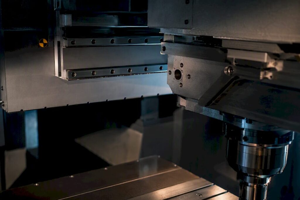
Machine tool rigidity is a structure’s resistance to deflection under cutting load, split into static stiffness and dynamic stability. The weak link in the structural loop, usually the spindle/tool-holder interface or a guideway joint, sets what the whole machine can actually achieve. Measure there first, using modal/FRF testing and a stiffness workspace map, before adding a gram of extra casting.
TL;DR:
- Focus testing on joints, interfaces, and guideways, as these common weak points often limit overall machine rigidity more than the castings or frames.
- Use static, frequency response, and workspace mapping measurements to accurately assess both position-dependent static and dynamic stiffness across the work envelope.
- Target reinforcement efforts on the most sensitive components identified through sensitivity analysis, rather than broad structural thickening, to improve dynamic behavior efficiently.
- Improve rigidity by verifying tool-holder seating, reducing tool overhang, checking guideway preload, and enhancing fixturing stability before considering costly redesigns.
- Confirm simulation models with real-world FRF and modal data to ensure accurate prediction of structural behavior and guide effective stiffness improvements.
Table of Contents
- What does machine tool rigidity actually mean?
- Why rigidity matters for precision and productivity
- Which components actually control rigidity?
- How do you measure rigidity in practice?
- Where should optimisation effort actually go?
- What practical steps improve rigidity and suppress chatter?
- How do you validate a rigidity design before it’s built?
- Notes from applying this on the shop floor
- Choosing a machine built for the rigidity your work demands
- Sources
What does machine tool rigidity actually mean?
Rigidity is a load-to-deflection ratio, reported in N/µm or N/mm, and the direction of that load matters as much as its magnitude. A machine that resists 500 N/µm in the X axis might sag badly under the same load applied diagonally through the spindle nose. That’s why a single stiffness number on a spec sheet is close to meaningless without the axis and location it was measured at.
Static (or quasi-static) stiffness describes how the structure deflects under a steady push. Dynamic stiffness is frequency-dependent. It describes how the structure responds when that load oscillates near a natural frequency, which is the condition that actually produces chatter. The two rarely track each other neatly, because damping and mass distribution affect dynamic response in ways a slow-speed static test never reveals.
Rigidity is also position-dependent across the work envelope. A gantry machine can be stiff at the column but soft at full Z extension, and a proper stiffness report gives readings for X, Y, Z translation and rotational compliance at several representative points, not one number for the whole machine.
Why rigidity matters for precision and productivity
Stiffness sets the ceiling on dimensional accuracy and repeatability, because every cutting force deflects the tool away from its programmed path by an amount proportional to structural compliance. A softer machine chases a tighter tolerance and loses, no matter how good the controller is. This is one reason tight CNC tolerances demand structural rigidity as much as good programming.
Chatter is the more dramatic consequence. Below a critical depth of cut, cutting stays stable; cross that threshold and self-excited vibration takes over, tearing the surface finish and shortening tool life within seconds. Damping raises that stability limit directly. Workpiece-mounted mass dampers have shown stability improvements of up to 45 times in tested thin-walled finishing cases, according to research on pneumatic mass dampers, a scale of improvement that reframes damping as a productivity lever, not a nice-to-have.
Pro Tip: If a part fails a surface finish check intermittently rather than consistently, suspect a chatter threshold problem before you suspect the program. Consistent errors point to static compliance; intermittent ones point to dynamic instability.
Which components actually control rigidity?
Designers routinely blame the wrong part. The casting gets thickened, the ribs get redesigned, and the actual soft spot, often a joint or an interface, goes untouched. Static testing alone frequently misses this, because joint non-linearities and bearing preload behave differently under dynamic load than under a slow push.
The elements worth checking, roughly in order of how often they turn out to be the limiting factor:
- Frame and casting geometry — mass distribution and rib layout set the baseline structural loop stiffness.
- Ways and guide systems — boxways use large contact area to combine high stiffness with strong vibration damping. Linear guides move faster but carry less inherent damping and often need it added elsewhere.
- Spindle and tool-holder interface — this is where compliance concentrates in most production machines, and a poor taper fit or excessive overhang will undo an otherwise rigid frame.
- Joints and preload — bolted connections, bearing preload and slideway clamping introduce non-linear stiffness that a purely elastic model will not predict.
Fixturing strategy compounds all of the above. A workpiece that is under-clamped adds its own compliance to the loop, which is why zero-point fixturing approaches earn their keep on rigidity-sensitive jobs, not just on setup speed.
How do you measure rigidity in practice?
Measurement should follow a defined sequence rather than an ad hoc push test, because inconsistent methodology is one of the biggest reasons stiffness figures from different sources can’t be compared honestly.
- Quasi-static loading. Apply a known force at the tool tip or spindle nose using a calibrated hydraulic ram or dead weights, and measure deflection with dial indicators or laser interferometry. Divide force by deflection to get N/µm, and record the load direction and location every time.
- Frequency response function (FRF) testing. Excite the structure with an impact hammer or shaker and capture the response with an accelerometer. Peaks in the FRF mark natural frequencies; peak height and width tell you damping at each mode.
- Experimental modal analysis. Extend the FRF data across multiple points to build mode shapes, which show where the structure moves most at each resonance, usually the clue to which component to fix.
- Workspace stiffness mapping. Repeat static and dynamic tests at several positions across the work envelope using a Stiffness Workspace System (SWS) approach, since a single-point reading hides exactly the position dependence that catches designers out later.
The report worth handing to a vendor or client states load direction, measurement location, uncertainty bounds, and whether the figure is static or dynamic. Anything less invites a comparison that isn’t actually valid.
Where should optimisation effort actually go?
Dynamic stiffness sensitivity analysis identifies which specific components most influence a machine’s position-dependent dynamic behaviour, rather than treating the whole structure as equally deserving of reinforcement. Work verified on a five-axis gantry machine showed that a small subset of sensitive parts effectively represents the dynamic behaviour of the whole machine, which means fixing those parts buys most of the available performance gain.
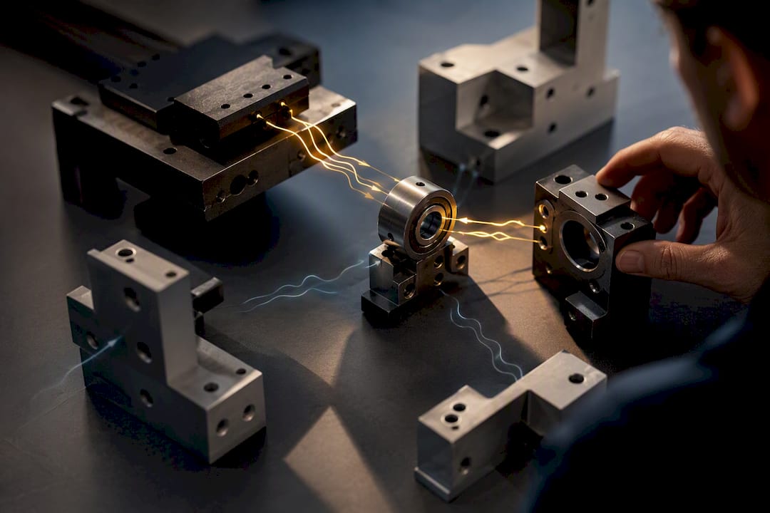
This challenges the instinct to add mass everywhere. Thickening a casting that isn’t actually sensitive spends weight and cost for close to nothing, while a targeted fix on the true bottleneck, often a joint, a bearing preload setting, or a thin bracket near the spindle, can outperform a much larger structural change.
Pro Tip: Before specifying any structural rework, run a sensitivity study first. It typically costs a fraction of a redesign cycle and tells you exactly which three or four components are worth touching.
Where sensitivity analysis flags a genuine vibration problem rather than a static stiffness gap, damping is usually the more efficient fix than stiffening. Tuned mass dampers and particle dampers both add vibration absorption without the mass penalty of a thicker casting. Active vibration control goes further still, using proof-mass actuators to cancel vibration in real time, with documented amplitude reductions of around 44% at critical frequencies in ultra-precision applications. The catch is commissioning: tuning an active system properly takes genuine expertise, which is why uptake still lags the hardware’s proven capability.
What practical steps improve rigidity and suppress chatter?
Start with the cheapest, fastest checks before reaching for a redesign:
- Check tool-holder seating and taper contact; a poorly seated holder can dominate the entire stiffness budget on its own.
- Reduce tool overhang wherever the operation allows it, since compliance grows roughly with the cube of overhang length.
- Verify guideway and bearing preload against spec; preload that has relaxed over time quietly erodes stiffness with no visible symptom until chatter appears.
- Improve fixturing rigidity, particularly on thin-walled or asymmetric parts where the workpiece itself is often softer than the machine holding it.
If those checks don’t resolve the issue, moderate-effort measures come next: embedded or particle dampers, revised fixturing strategy, or a change to guideway lubrication and preload settings. Particle damping combined with a genuinely lightweight structure has been shown to hold acceptable dynamic performance on a heavy-duty CNC lathe without piling on mass, which matters for energy use and material cost alike.
Pro Tip: Treat structural redesign, tuned mass dampers and active control as a last resort, not a first move. They’re effective, but the ROI only shows up once cheaper fixes are exhausted.
Advanced measures, tuned mass dampers, active control, or a full structural redesign backed by FEA, carry real trade-offs between weight, damping and throughput. A stiffer, heavier structure often costs speed and energy; a lighter one needs smarter damping to match it.
How do you validate a rigidity design before it’s built?
Simulation only earns trust when it matches reality, and that means modelling the parts of the structure most engineers skip. FEA that represents only the castings and ignores joint contact, bolted interfaces and guideway preload will predict a stiffer machine than the one that actually gets built, because contact non-linearities and preload soften real structures in ways idealised solid models cannot capture.
Correlate the model against FRF and modal test data from a physical prototype or a closely related existing machine. If predicted mode shapes and frequencies don’t line up with measured ones, the model needs revised joint stiffness values, not a finer mesh. Iterate until the key modes, usually the first two or three, agree within a reasonable margin.
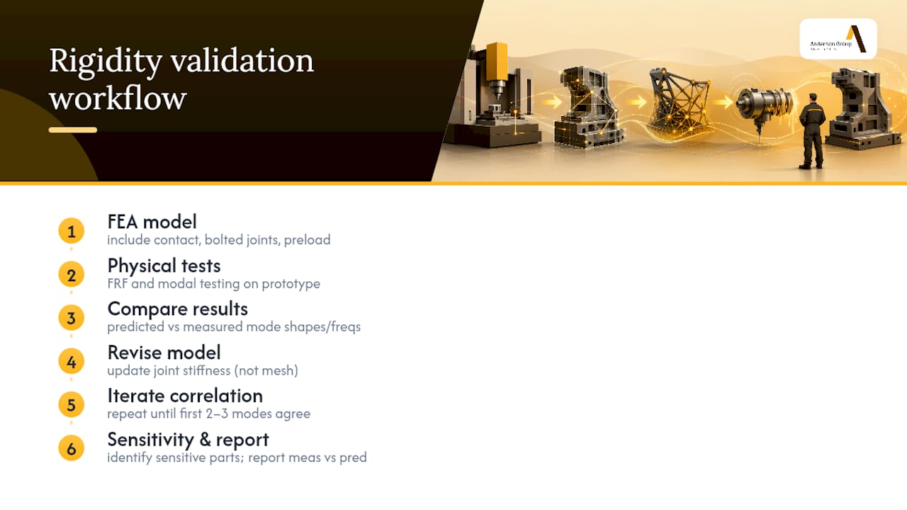
Sensitivity studies run on the correlated model then tell you which retrofit or design change gives the best return before you cut metal. The report worth sharing with a vendor states measured versus predicted mode frequencies, damping ratios, and the specific components flagged as sensitive, giving both sides a shared, checkable basis for the design decision.
Notes from applying this on the shop floor
Engineers in the industry treat a stiffness check as the first conversation, not the last. Clients often bring surface finish complaints when the real story is a relaxed preload or an overhung tool. The most useful thing a designer can bring to that meeting is actual FRF data from the problem operation, not just a part drawing.
Expect a proper measurement pass to take a few hours on-site, not minutes, and expect the deliverable to be a stiffness map with uncertainty bounds, not a single number. Anything faster than that is a guess dressed up as a measurement.
— Scott
Choosing a machine built for the rigidity your work demands
Many leading manufacturers build CNC platforms where stiffness is engineered into the frame, guideways and spindle interface from the outset, not bolted on afterwards. For manufacturers weighing box way versus linear guide trade-offs on a new purchase, that structural groundwork matters more than any spec sheet number in isolation.

Where cutting loads are heavy and damping matters more than rapid traverse, platforms like the MAXXIS 5-axis range and the MASS-5 large-scale machining centre are specified with exactly this loop in mind, and Anderson’s teams can run on-site stiffness and modal testing on existing equipment to pinpoint where a retrofit will pay off before you commit budget to a full replacement. If tool-holder or spindle interface stiffness is suspect, checking spindle options against your cutting profile is worth doing before any structural rework.
Contact a suitable CNC machinery provider to arrange a technical consultation or an on-site measurement session, and bring your current FRF or chatter data if you have it. It shortens the path to the right fix considerably.
Sources
- Dynamics of machine tools based on dynamic stiffness sensitivity (Processes)
- Which way is right? (American Machinist)
- Broadband pneumatic mass damper for elimination of workpiece vibrations (ScienceDirect)
- Active vibration control development in ultra‑precision machining (SAGE Journals)