
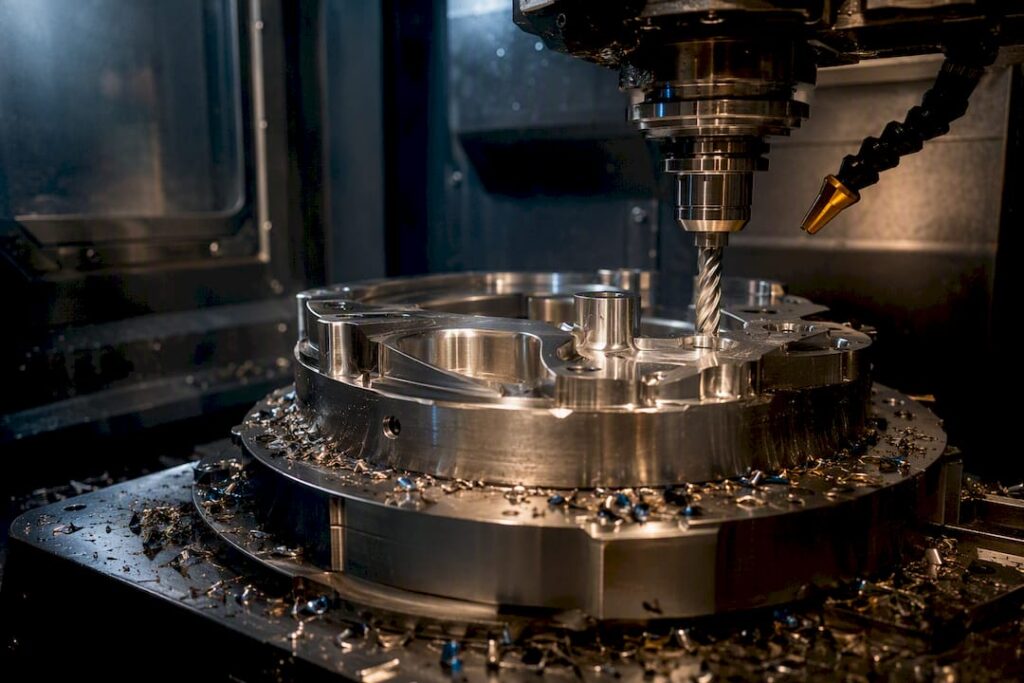
Yes, titanium and Ti-6Al-4V machine reliably on CNC once you control heat, hold a minimum chip load, and match tooling and coolant to the alloy. Anderson Group Australia’s production experience across aerospace and general engineering backs three shop rules for the first cut: run conservative SFM without ever letting chip load drop into the rubbing zone, get coolant through the tool at real pressure, and lock the part down with a rigid, chatter-free setup before you touch the cycle start button.
TL;DR:
- Precise heat control, sufficient chip load, and proper coolant pressure are essential to reliably machine titanium on CNC machines, especially for high-volume production.
- Using dedicated, well-maintained carbide tools with appropriate coatings and short overhangs minimizes wear and prevents sudden edge failure during titanium cutting.
- High-pressure coolant delivery and, for large volumes, cryogenic systems significantly extend tool life by effectively dissipating heat at the cutting edge.
- Consistent discipline in tool inspection, chip load verification, and part cooling before measurement is crucial to maintaining quality and avoiding scrap.
- Heavy, rigid machine setups with proper support for thin walls and vibration control are necessary for stable, chatter-free titanium machining.
Table of Contents
- Titanium machining CNC starting feeds, speeds and chip loads
- How alloy choice affects machinability and part design
- Tooling and coatings for titanium: carbide grades and geometry
- Coolant strategy: from flood to cryogenic
- Workholding, rigidity and vibration control
- CAM strategies for titanium: trochoidal and HEM control
- Drilling, boring and threading titanium parts
- Tolerances, surface finish and inspection timing
- Safety, fire risk and tool wear thresholds
- Anderson Group Australia’s machine classes for titanium production
- Predictive maintenance and wear monitoring for titanium tooling
- Post-machining inspection methods for titanium components
- Environmental and disposal considerations for titanium machining waste
- What actually separates good titanium shops from struggling ones
- How Anderson supports titanium production without the guesswork
- Sources
Titanium machining CNC starting feeds, speeds and chip loads
Titanium punishes guesswork more than most alloys, so the numbers below are a starting point, not a finished program. Ti-6Al-4V and CP Grade 2 behave differently enough that using one chart for both is how tools die early.
| Operation | Alloy | SFM range | Chip load |
|---|---|---|---|
| Roughing (HEM) | Ti-6Al-4V | 100–150 SFM | 0.004–0.006 in/tooth |
| Roughing (HEM) | CP Grade 2 | 150–200 SFM | 0.005–0.007 in/tooth |
| Conventional slotting | Ti-6Al-4V | 80–120 SFM | 0.003–0.005 in/tooth |
| Finishing | Ti-6Al-4V | 120–160 SFM | 0.002–0.004 in/tooth |
A 2026 feeds and speeds reference sets these ranges for Ti-6Al-4V and Grade 2 and recommends chip-thinning compensation before you release a program to the floor. Three things to keep in mind before trusting any chart:
- Machine rigidity and spindle taper change what’s actually achievable, sometimes by 20% either way.
- Toolholder runout above roughly 0.0005 in. destroys tool life faster than pushing SFM ten percent high.
- Always cut a short validation pass and check chip colour and edge wear before committing to full-depth passes.
How alloy choice affects machinability and part design
Grade 2 and Grade 5 aren’t interchangeable just because they’re both titanium. CP Grade 2 has slightly higher thermal conductivity and lower strength, so it cuts a little easier and tolerates marginally higher SFM. Ti-6Al-4V and its ELI variant machine tougher because the vanadium and aluminium content raises strength and hardness while dropping conductivity further, concentrating heat right at the cutting edge.
- Choose Grade 2 where corrosion resistance is the priority and strength requirements are modest, such as chemical process fittings.
- Choose Grade 5 or ELI where strength-to-weight matters, such as aerospace brackets or medical implants, and budget for slower cycles.
- Design thicker fillet radii and avoid thin unsupported walls wherever possible. Titanium’s springback under load turns a marginal wall thickness into a chatter problem you didn’t plan for.
Tooling and coatings for titanium: carbide grades and geometry
Coated cemented carbide is the default for almost all titanium work. ISCAR’s machining guide recommends PVD TiAlN or AlTiN coatings because they hold hardness at the elevated edge temperatures titanium generates, and it specifically calls out internal coolant delivery and solid carbide endmills as the combination that resists chatter best.
- Use 4 to 6 flute solid carbide endmills with a variable helix for roughing; fewer, sharper flutes for finishing where chip evacuation matters more than material removal rate.
- Favour a sharp, positive rake insert geometry with a honed (not heavily chamfered) edge. Titanium doesn’t need a tough edge, it needs a sharp one that avoids work hardening the surface.
- Uncoated carbide still has a place in low-speed finishing passes where coating flaking risk outweighs any wear benefit.
- Retire inserts and endmills before flank wear (VB) exceeds roughly 0.15 to 0.2 mm. Pushing past that point in titanium tends to cause sudden edge failure rather than gradual wear.
Pro Tip: Keep a dedicated tool crib for titanium work. A carbide endmill that’s cut aluminium first, even briefly, often has a subtly rounded edge that won’t show up until it’s already scorching your titanium finish pass.
Coolant strategy: from flood to cryogenic
Titanium’s thermal conductivity sits around 6.7 to 7 W/m·K, roughly a sixth that of steel, which means close to 80% of cutting heat stays at the tool edge instead of dissipating into the chip or workpiece. That single fact drives nearly every other decision in this guide, from chip load floors to coating selection.
- Standard flood coolant works for light, occasional titanium work but rarely keeps pace with sustained production cuts.
- Through-tool high-pressure coolant at 500 to 1,000 psi (roughly 35 to 70 bar) is the practical workhorse tier for shops cutting titanium regularly.
- Cryogenic systems (liquid nitrogen or CO2) push tool life further again but only make financial sense at very high daily volumes.
- Aim nozzles to follow the chip curl, not just the tool tip, so coolant actually reaches the shear zone rather than bouncing off the flute.
Hymson’s guidance on thermal management notes that a through-spindle HPC retrofit at typical production pressures can pay back through extended tool life and reduced scrap for shops with weekly titanium work, generally within a one- to two-year timeframe. That’s a meaningfully faster payback than cryogenic setups, which only earn their keep at much higher daily volumes.
Workholding, rigidity and vibration control
Titanium’s springiness under cutting load is the part most engineers underestimate until they’ve fought it. A maker-shop perspective from Tormach points out that small VMCs with lighter spindles and less rigid columns struggle with chatter that a production-class machine simply shrugs off.
- Match machine class to volume. Occasional titanium parts can run on a well-tuned VMC; regular production work justifies a heavier spindle taper and a more rigid column.
- Support thin walls and small parts with wax fill, vacuum fixturing, or sacrificial webbing rather than relying on clamping force alone.
- Keep tool overhang as short as the geometry allows. Every extra millimetre of stickout multiplies deflection under load.
- Choose anti-vibration or damped toolholders for deep pocket or thin-wall work where chatter risk is highest.
CAM strategies for titanium: trochoidal and HEM control
Constant engagement toolpaths change the physics of the cut, not just the programming. Allied Metal Solutions’ case data shows that trochoidal and high-efficiency milling toolpaths measurably lower peak cutting forces and notch wear compared with conventional slotting, because the tool never buries itself fully into the material at any one point.
- Set radial engagement between 10% and 25% of tool diameter for HEM roughing, then compensate feed rate for chip thinning at those lower engagement angles.
- Use ramp or helical entries rather than plunging straight down; a stationary plunge concentrates heat exactly where you don’t want it.
- Program exits that lift the tool clear rather than dwelling, since any pause under load in titanium invites work hardening at that exact spot.
Skipping this step is the single most common reason HEM programs run tools hotter than expected.*
Drilling, boring and threading titanium parts
Holemaking rules diverge from milling because chip evacuation gets harder as the hole deepens. Use a drill point geometry with a split point or notched design to reduce walking, and peck at shallow increments once depth exceeds roughly three diameters, always with through-tool coolant if the machine and holder support it.
- Bore and ream in a final pass with slightly increased clearance to allow for elastic spring-back, since titanium recovers more after the tool passes than aluminium or steel.
- Thread mill rather than tap wherever tolerance control matters, particularly for blind holes where chip packing is the main tap failure mode.
- Keep peck retraction fast enough to clear chips fully; a partial retraction just repacks the hole.
Tolerances, surface finish and inspection timing
Finish tolerances of roughly ±0.01 mm and Ra 0.8 µm are realistic with fresh inserts and controlled thermal input, based on production shop data. Finish critical features in a single clamping wherever possible, since titanium’s low conductivity means the part holds residual heat longer than steel does at the same size. Where tight tolerances matter, let the part stabilise to room temperature before final measurement rather than gauging it straight off the spindle.
Safety, fire risk and tool wear thresholds
Titanium chips and fines are a genuine fire risk, particularly fine swarf from finishing passes. Store chips in sealed metal containers away from other combustible waste, and keep a Class D extinguisher rated for metal fires within reach of any titanium-dedicated cell.
- Check flank wear (VB) at first-part inspection and again every 10 to 20 parts depending on cut severity.
- Replace tooling once VB approaches 0.15 to 0.2 mm rather than running to visible chipping.
- Escalate immediately if you hear chatter increase mid-run. It’s usually the first sign of tool wear, not a fixture problem.
Anderson Group Australia’s machine classes for titanium production
Rigidity and coolant delivery are machine problems as much as programming problems. Production-class centres with heavier spindle tapers and integrated high-pressure coolant plumbing handle titanium’s demands more consistently than lighter-duty machines pressed into service beyond their design intent. Anderson’s production machining centres and 5-axis platforms are built with the spindle power and structural mass this alloy needs, and Anderson’s service team supports HPC retrofits and toolholding upgrades for shops trying to extend an existing line into titanium work without starting from scratch.
Predictive maintenance and wear monitoring for titanium tooling
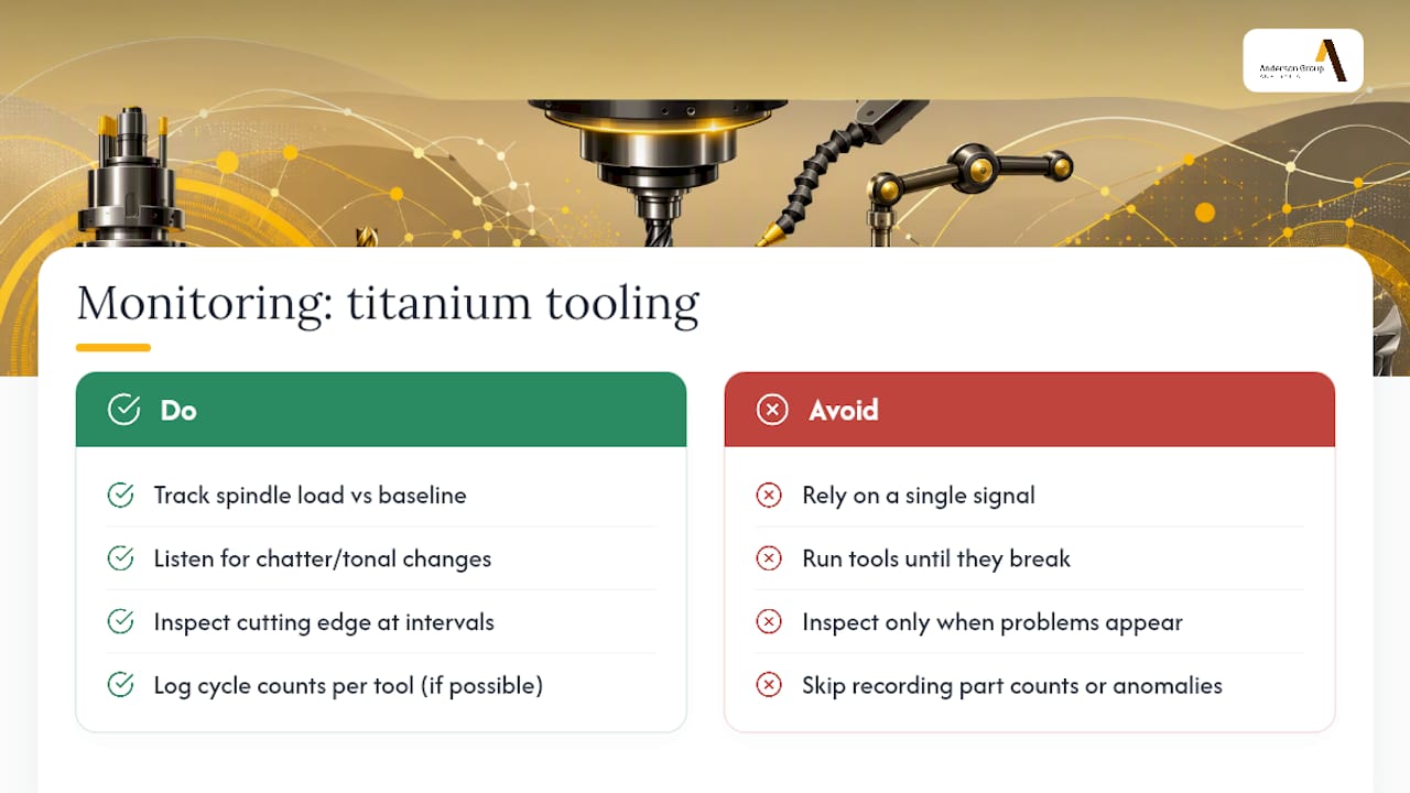
Titanium tools rarely wear gradually and predictably the way they do in aluminium or mild steel. Flank wear can look stable for dozens of parts and then progress to catastrophic edge failure within one or two cycles once it crosses a threshold, because the heat concentrated at the edge accelerates once the coating layer is breached. That non-linear failure curve is why reactive tool changes (“run it till it breaks”) cost more in titanium than in almost any other common alloy, through scrapped parts, damaged fixtures, and unplanned downtime.
A workable monitoring routine combines three checks rather than relying on any single signal. First, track spindle load or power draw against a baseline for that specific operation. Second, listen for chatter or tonal change during the cut. Titanium chatter tends to announce itself audibly before it shows up as a dimensional or finish problem. Third, physically inspect the cutting edge under magnification at fixed part-count intervals rather than only when something looks wrong.
Where budget allows, tool life management software tied to the machine control can log cycle counts per tool and flag replacement before the wear curve turns steep. For shops without that infrastructure, a simple logbook tracking part count, observed wear, and any load anomalies per tool achieves most of the same benefit. The goal in either case is catching the wear curve while it’s still gradual, not after it has already gone vertical.
Post-machining inspection methods for titanium components
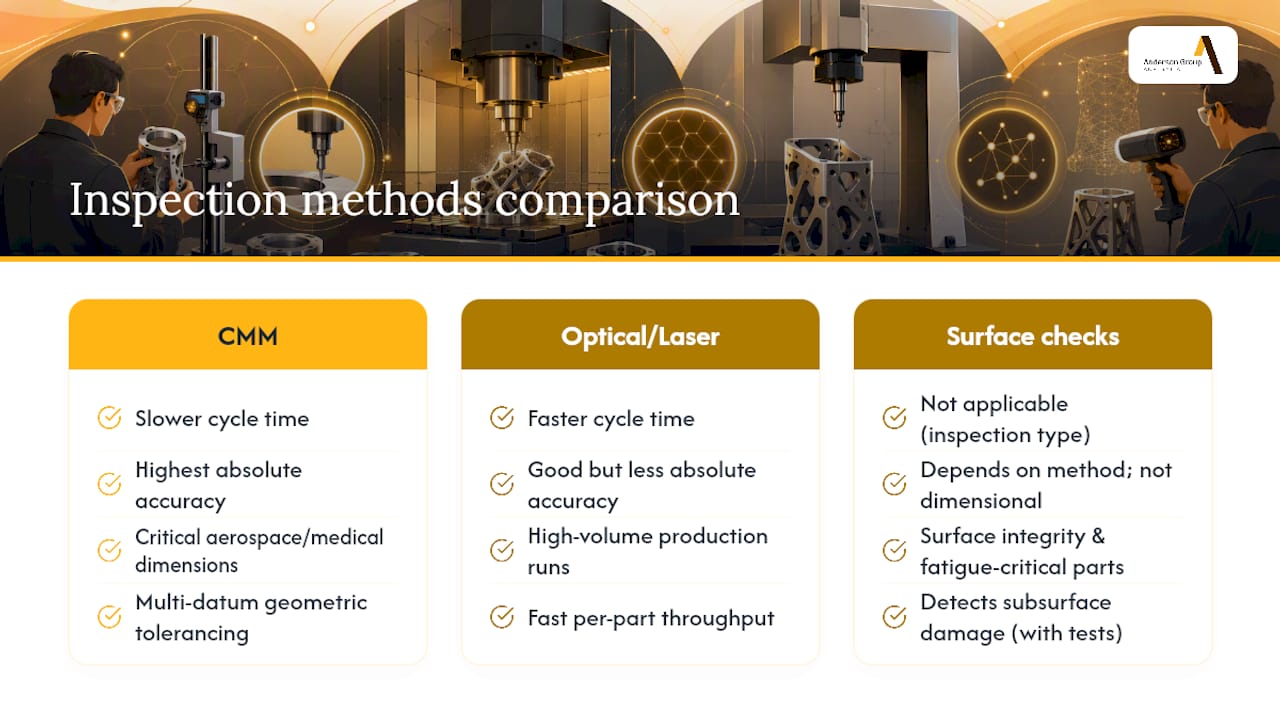
Titanium parts need an inspection plan that accounts for the material’s tendency to hold heat and to spring back elastically after machining, both of which can produce false readings if measurement happens too early. Letting a part cool to ambient temperature before final dimensional checks avoids the small but real thermal expansion error that shows up when gauging a part straight off the spindle, particularly on tight tolerance bores and bosses.
Coordinate measuring machines (CMMs) remain the standard for verifying critical dimensions on aerospace and medical titanium components, especially where geometric tolerancing on multiple datums matters. For high-volume production runs, optical or laser scanning systems offer faster cycle times per part, though CMM contact probing still tends to win on absolute accuracy for the tightest tolerance features.
Surface integrity checks matter more in titanium than in many other alloys because subsurface damage from excessive heat or a worn tool doesn’t always show on a surface finish reading. Where fatigue performance is critical, such as rotating aerospace components, some manufacturers run periodic destructive sectioning or non-destructive eddy current testing to check for the white-layer microstructural changes that thermal damage can cause beneath an otherwise acceptable surface. Visual inspection under magnification, paired with a surface roughness gauge for Ra verification, covers the baseline requirement for most general engineering titanium parts. First-off inspection on any new setup should always include a dimensional check plus a visual review of the cut surface for any discolouration, which is often the first visible sign of excess heat even when the part still measures within tolerance.
Environmental and disposal considerations for titanium machining waste
Titanium swarf and chips carry real value as scrap, which changes both the economics and the handling requirements compared with disposing of other metal waste. Clean, segregated titanium chips command a meaningful price from specialist metal recyclers, so keeping titanium swarf separate from aluminium, steel, or mixed-alloy waste streams pays for itself rather than being a compliance-only exercise.
Fine titanium fines pose the same fire risk in the waste stream as they do at the machine, so storage containers need to be sealed, metal, and kept away from other combustible material until collection. Coolant contamination is the other practical issue. Titanium fines suspended in cutting fluid accelerate fluid breakdown and can affect filtration systems differently than steel or aluminium swarf does, so many shops run dedicated coolant systems or more frequent filtration cycles on cells dedicated to titanium work.
Used cutting fluid itself falls under standard industrial waste handling requirements and should be disposed of through a licensed waste contractor rather than general trade waste, given the metal content and any tramp oil contamination from machine lubrication. Worn carbide tooling also carries recycling value; carbide reclaimers pay for tungsten content, making scrap tooling collection worth organising alongside chip recycling rather than sending it to general waste.
What actually separates good titanium shops from struggling ones
The gap between shops that machine titanium profitably and those that fight it every run usually isn’t tooling knowledge. Most engineers can quote SFM ranges from memory. The gap is discipline around the boring stuff: actually checking chip load against the rubbing threshold before running a new program, actually inspecting the edge at set intervals instead of waiting for a bad part, actually letting a part cool before final gauging instead of rushing the inspection to hit a shipping deadline.
Titanium doesn’t punish ignorance so much as it punishes shortcuts. A shop that runs conservative parameters consistently will beat a shop chasing aggressive numbers that occasionally works and occasionally scraps a $400 forging.
Before the first production run, walk through alloy grade, tooling and coating selection, coolant pressure at the nozzle (not just at the pump), fixture rigidity, and the measurement plan. Watch the first five parts closely: if spindle load creeps upward, chatter appears, or finish degrades, stop and adjust rather than pushing to part six on the same worn edge.
— Scott
How Anderson supports titanium production without the guesswork
Getting the parameters right on paper only gets you halfway. The machine still needs the rigidity, spindle power, and coolant delivery to hold those numbers under real cutting load, which is where a lot of titanium programs quietly fail even with good CAM work behind them.

Anderson’s AXXIOM 5-axis series and MASS-5 large-scale 5-axis centre are built with the structural mass and spindle capability titanium demands, and the production machining centre with APC adds pallet automation for shops running titanium in volume rather than one-off. For manufacturers already running a line and looking to add high-pressure coolant or upgrade toolholding rather than replace a machine outright, Anderson’s service team can scope a retrofit against your current cell. If you’re weighing up whether your next titanium contract needs a new machine or a targeted upgrade, get in touch with Anderson’s metalwork CNC machinery team for a straight answer based on your part mix and volume.
Sources
- Machining Titanium (ISCAR)
- Titanium Feeds & Speeds Chart 2026: Ti-6Al-4V, CP Grade 2 & HEM | CNC Optimization
- Titanium CNC Machining Optimization | Ti-6Al-4V Feeds, Speeds & Thermal Management Solutions
- CNC Machining Titanium: Challenges, Strategies & Cost Guide for Aerospace, Medical & Performance Parts – Allied Metal Solutions
- CNC materials: the truth about titanium Machining