
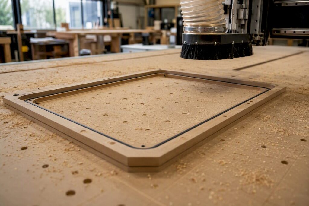
Vacuum hold-down should be assessed against the part size, contact area, material porosity, cut sequence and expected cutting loads. Small parts, through-cuts or leakage can change the result, so ask how the proposed table, pump, zoning and any supplementary restraint will be verified on representative work. For cabinet production, compare these requirements when reviewing the Genesis PLUS nesting CNC machine; confirm the workholding configuration rather than assuming every setup is identical.
The physics sets a hard ceiling: atmospheric pressure at sea level caps holding force at 14.7 psi theoretical maximum, and no pump on earth pushes past that. Everything in vacuum fixture design is about getting as close to that number as practical, then engineering around what’s left.
-
Best fit: large flat sheets, thin panels, non-porous materials, jobs needing full top-surface access
-
Poor fit: small parts, porous timber, sintered metals, deep pocketing with high side loads
-
Primary limits: sealed area, seal integrity, lateral force resistance, altitude
Anderson has built CNC platforms around exactly these workholding trade-offs for decades, and the rest of this guide breaks down the engineering behind getting vacuum fixturing right in your own shop.
Key Takeaways
Reliable vacuum fixturing depends on matching sealed contact area and seal quality to cutting loads, not on chasing the highest possible inHg reading.
| Point | Details |
|---|---|
| Know the ceiling | 14.7 psi is the sea-level theoretical maximum; real pumps deliver roughly 10–13 psi in practice. |
| Groove depth rule | Cut O-ring grooves at 70–85% of O-ring diameter for a proper compression seal. |
| Size chambers correctly | Keep chamber volume at least 3× pump displacement for fast, consistent evacuation. |
| Apply a safety factor | Use a 2× safety margin on calculated hold-down force before setting cutting parameters. |
| Scale with the right platform | Anderson’s pallet-changing and nesting machines support vacuum fixturing workflows from prototyping through to production volume. |
Table of Contents
-
Designing the seal: O-rings, grooves, and spoilboard porosity
-
Setup checklist and best practices that actually prevent failures
-
Where vacuum fixturing falls short and how hybrid setups fix it
-
Programming toolpaths and automation around vacuum fixturing
-
Editorial take: the engineering discipline vacuum fixturing actually demands
-
Get vacuum-ready CNC platforms built for production, not prototyping
-
Frequently asked questions about vacuum fixturing CNC setups
How vacuum fixturing CNC hold-down actually works
Vacuum fixturing doesn’t “suck” a part down with some mysterious force. It removes air from a sealed chamber beneath the part, and atmospheric pressure above pushes down on the exposed surface to fill that pressure differential. That’s the entire mechanism, and it’s why the numbers matter so much more than intuition here.
At sea level, atmospheric pressure caps out at 14.7 psi. Your pump never touches that figure. A typical shop pump pulling 20 to 28 inches of mercury (inHg) delivers roughly 10 to 13 psi of usable holding pressure, once you account for real-world seal losses and porous spoilboard leakage.
Statistic callout: A pump running at 25 inHg delivers usable holding pressure across a sealed area, meaning a 1-square-foot (144 square inch) zone holds a significant theoretical force before any safety margin.
-
14.7 psi is the absolute physical ceiling, not a design target
-
20 to 28 inHg pump output translates to roughly 10 to 13 psi in practice
-
Every inch of altitude above sea level drops available pressure further
Altitude reduces the atmospheric pressure differential available to your system, so a shop at 1,500 metres elevation is working with meaningfully less holding force than one at sea level, even with an identical pump. Compensate by increasing sealed contact area, tightening seal quality, or stepping up to a higher-flow pump rather than assuming your gauge reading tells the whole story.
Which materials and part geometries suit vacuum fixturing
Vacuum fixturing rewards non-porous, dimensionally stable stock with a flat reference face. Aluminium sheet, cast acrylic, solid engineering plastics, and most composite laminates hold reliably because air can’t migrate through the material itself and defeat your seal.
Porous materials fight you from the start. Raw MDF, particleboard, and sintered or powdered metals leak air through their own structure, which forces your pump to work harder just to maintain baseline vacuum, let alone holding force. Timber with open grain running to an edge behaves the same way.
-
Reliable: aluminium, cast acrylic, solid engineering plastics, dense composites, sealed or coated timber panels
-
Poor performers: raw MDF, particleboard, sintered metals, open-grain timber near edges
-
Minimum contact area: aim for enough sealed surface to generate holding force well above your expected cutting loads, not just barely enough
A practical rule most shops use: if a part’s flatness deviates more than a few thousandths across the sealed zone, you’re relying on the gasket to bridge a gap it wasn’t designed for. Check your material compatibility before committing a job to vacuum, and for warped or dusty stock, clean the surface and check the spoilboard for pitting or debris that will telegraph straight through the seal.
Designing the seal: O-rings, grooves, and spoilboard porosity

Seal design is where most vacuum fixturing setups actually fail, not in the pump specification. Get the groove and gasket geometry wrong and no amount of pump capacity fixes it.
The standard rule for O-ring grooves is depth equal to 70 to 85% of the O-ring’s diameter. Too shallow and the seal can’t compress properly against an uneven surface; too deep and it never makes contact at all. For a common 3/16-inch O-ring, that puts groove depth in the 0.130 to 0.160-inch range.
-
Perimeter O-ring seals work well for single large parts where the whole boundary needs one continuous vacuum zone.
-
Grid channel systems distribute vacuum across the plate in a network, typically 0.125 to 0.250 inches wide and 0.050 to 0.100 inches deep, suited to irregular or multiple smaller parts.
-
Hybrid layouts combine a perimeter seal with internal grid channels for parts with cutouts or islands that would otherwise create dead zones.
Porous spoilboards are the quiet killer of vacuum performance. Sealing the surface with shellac, dedicated tape, or a sacrificial mat cuts leakage significantly, and treating the spoilboard is standard practice in shops running vacuum daily. Resurface or reseal on a schedule tied to your job volume, not a calendar date.
Pro Tip: Cut a test groove in scrap stock at your target depth and press a sample O-ring into it by hand before committing the full fixture plate. If it seats flush without bulging, your groove geometry is right.
Choosing a pump: flow, vacuum level, and plumbing basics
Pump choice depends less on raw vacuum level and more on how much air volume it can move, especially once porous spoilboards or slightly imperfect seals are in the picture.
Venturi pumps are cheap and have no moving parts, but they’re compressed-air hungry and weak on flow, best for small, well-sealed jobs. Diaphragm pumps offer a decent middle ground for light-duty benchtop setups. Side-channel (regenerative) pumps deliver strong continuous flow at moderate vacuum, which suits nesting operations on porous MDF spoilboards well. Rotary vane pumps hit the highest vacuum levels and handle multi-zone production work, though they need oil maintenance and cost more upfront.
-
High airflow matters more than peak vacuum when your spoilboard is porous, because the pump is constantly replacing air leaking through the board itself
-
Size hose and port diameter generously; undersized plumbing throttles flow regardless of pump capacity
-
Zone isolation valves let you shut off unused areas of a large table, concentrating available vacuum where the part actually sits
Every serious setup needs a vacuum gauge mounted where the operator can see it mid-cut, a ball valve for manual zone control, and a check valve to prevent backflow if the pump loses power unexpectedly.
Calculating hold-down force and chamber volume
The core formula is simple: hold-down force = pressure differential × sealed area. Everything else in vacuum fixture design is just making sure that number comfortably exceeds your expected cutting forces.
Take a pump delivering 25 inHg, roughly 12.3 psi of usable pressure. A sealed zone of 100 square inches gives you 1,230 pounds of theoretical holding force. Apply a 2× safety factor, standard practice for anything beyond light finishing passes, and your reliable working capacity drops to around 615 pounds, which is the figure you should actually design cutting parameters against.
| Parameter | Guideline |
|---|---|
| Vacuum level | 20–28 inHg typical shop range |
| Usable pressure | ~10–13 psi after seal losses |
| Safety factor | 2× minimum on calculated hold-down force |
| Chamber volume | At least 3× pump displacement |
| Hose inner diameter | Match or exceed pump port size, no unnecessary reductions |
Statistic callout: Chamber volume should be at least 3 times the pump’s displacement to achieve rapid, consistent evacuation rather than a slow crawl to working vacuum on every cycle.
Setup checklist and best practices that actually prevent failures
A vacuum fixturing job lives or dies on setup discipline. Skip a check and you’ll find out mid-cut, which is the expensive way to learn.
-
Clean the spoilboard and part surface. Chips, dust, and old adhesive residue are the single most common cause of slow leaks.
-
Pull vacuum and read the gauge before starting the program. If it doesn’t reach your expected range within a few seconds, stop and find the leak.
-
Run a manual leak check by listening and feeling along the perimeter seal and any grid channel joints.
-
Close off unused zones so vacuum concentrates where the part actually is.
-
Choose cutting strategy to match the fixture. High-helix or downcut end mills reduce the radial forces that cause lateral sliding on vacuum-held stock, and multiple shallow passes beat one aggressive pass every time.
-
For small parts, add traction mats, dowel pins, or sacrificial tabs rather than relying on vacuum alone.
Pro Tip: If a part is borderline on contact area, run a dry cycle at full spindle speed with the vacuum on but no cutting engaged. Watch for any shift before committing a live tool to the surface.
Limit spindle torque and feed rate on anything near your calculated hold-down limit rather than discovering the ceiling the hard way.
Where vacuum fixturing falls short and how hybrid setups fix it
Vacuum fixturing has real limits, and pretending otherwise costs you scrapped parts. Seal loss from debris or a damaged O-ring, part sliding under lateral cutting load, and pump deadheading from a closed or blocked line are the three failure modes you’ll see most often.
-
Seal loss: gauge drops mid-cut, check for debris, gasket damage, or a cracked plate
-
Sliding: part shifts under side-load, usually a sign contact area or cutting strategy needs revisiting
-
Motor deadheading: pump overheats from a fully sealed system with nowhere to pull air, a genuine fire and equipment risk
Mechanical locators or dowel pins alongside vacuum handle the lateral stability that suction alone can’t provide, particularly on thin-wall parts or 5-axis work where side loads shift constantly. This isn’t cheating, it’s how experienced shops actually run production. Humidity, coolant ingress, and altitude all degrade performance over time, so build in a gauge check as a standing habit rather than an occasional one.
Anderson’s role in reliable vacuum fixturing workflows
Anderson Group Australia supplies CNC machinery, servicing and spare parts. Confirm the exact machine configuration, installation arrangements and available support with the team.
-
Auto pallet changers with zero-point systems require confirmation of the proposed pallet, vacuum fixture and machine configuration. Review locating, workholding and setup requirements with Anderson Australia before selecting the arrangement.
-
5-axis platforms like AXXIOM handle the multi-angle access that vacuum-held thin panels often need
-
Nesting-focused machines suit flat panel work across furniture, cabinetry, and general engineering applications
If you’re scaling from a single vacuum table to a production cell, the fixturing principles here stay identical. Only the automation around them changes.
Keeping a vacuum system reliable over months of use
Vacuum fixturing systems degrade gradually, not suddenly, which is exactly why regular maintenance catches problems before they cost you a part. The spoilboard is the first thing to check. Repeated tool passes create micro-grooves and pitting that open new leak paths, so resurfacing on a schedule tied to job volume, not a fixed calendar date, keeps the sealing surface flat and predictable.

O-rings and gaskets harden and crack with age, especially where coolant or solvents contact them regularly. Inspect them visually every few weeks under normal shop use, and replace at the first sign of flattening, cracking, or permanent compression set rather than waiting for a gauge reading to confirm failure. A gasket that’s lost its memory won’t reseal properly even under full vacuum.
Pump maintenance depends on type. Rotary vane pumps need scheduled oil changes and filter checks, since oil contamination is the leading cause of premature pump wear. Side-channel and venturi pumps have fewer moving parts but still need intake filters cleared of dust, particularly in timber-heavy shops where airborne particulate is constant.
When troubleshooting a sudden vacuum drop, work through causes in order of likelihood: check the gauge first, then inspect the seal perimeter for debris or damage, then check hose connections and fittings for cracking, and only then suspect the pump itself. Most “pump failures” turn out to be a torn gasket or a loose fitting. Keep a log of gauge readings for recurring jobs. A gradual downward trend across weeks tells you a spoilboard or seal is wearing out well before it fails outright mid-cut.
Safety practices every vacuum fixturing operation needs
Vacuum fixturing introduces failure modes that mechanical clamping doesn’t, and treating it as inherently safer because there’s no visible clamp is a mistake that catches out even experienced operators.
The biggest risk is a part releasing mid-cut. If vacuum drops below the threshold needed to resist cutting forces, the part can shift or lift into a spinning tool with no warning beyond a gauge reading most operators aren’t watching in real time. Fit your control system with a vacuum interlock that pauses or stops the spindle automatically if pressure drops below a set threshold, rather than relying on an operator to notice.
Pump deadheading, where a fully sealed system leaves the pump with nowhere to pull air, causes overheating and is a genuine fire risk with rotary vane and diaphragm pumps left running unattended. Never leave a vacuum system pulling against a fully sealed, zero-flow condition for extended periods.
Coolant and cutting fluid ingress into vacuum lines is a secondary hazard: it degrades gaskets, contaminates pump oil, and in electrical setups near the pump motor introduces a shock risk. Route hose and plumbing away from the direct coolant spray path wherever the machine layout allows.
Finally, treat lateral load limits as a safety boundary, not just a quality one. A part that slides under cutting load doesn’t just ruin the job. It can catch a tool and send debris or a broken bit flying. When you’re near your calculated hold-down limit, add mechanical locators rather than pushing feed rates and hoping the seal holds.
Programming toolpaths and automation around vacuum fixturing
Vacuum fixturing changes how you should think about toolpath strategy, not just how you clamp the part. Because holding force depends entirely on sealed contact area, any toolpath that cuts through or near that sealed zone before the part is fully machined risks breaking the vacuum partway through the job.
Sequence operations so that features closest to the fixture’s sealed perimeter or grid channels are cut last, not first. Roughing passes that remove material near the edge of a sealed zone early in the program reduce your effective contact area for every subsequent pass, compounding risk as the job progresses.
For nesting and panel processing, most CAM software lets you define vacuum zones as part of the toolpath strategy itself, closing off zones as parts within a larger sheet are completed and cut free. This keeps vacuum concentrated on remaining, still-attached material rather than wasting pump capacity on an area that no longer needs holding.
Automation compounds the stakes. On a pallet-changing system, vacuum activation and verification need to be part of the automated cycle, not a manual step an operator confirms once and forgets. A pallet that swaps in without a confirmed vacuum seal, running unattended overnight, is a scrap part waiting to happen. Building a gauge check into the automated cycle start, so the program won’t proceed past a threshold pressure, is standard practice on production cells running vacuum-fixtured pallets continuously. Radial engagement strategy matters here too. Toolpaths using higher helix angles and consistent climb milling direction reduce the lateral forces that fight against your vacuum hold, letting automated cycles run with less risk of drift across an unattended shift.
Editorial take: the engineering discipline vacuum fixturing actually demands
Most vacuum fixturing advice online treats pump specification as the whole problem. It isn’t. The pump is the easiest part to get right and the least likely to fail. Seal design and surface preparation are where jobs actually go wrong, and that’s the part conventional advice glosses over in favour of comparing inHg ratings.
Get that wrong and no pump spec on earth saves the setup. The same goes for chamber volume at 3× pump displacement. Skip that and you’re fighting slow cycle times on every single job, blaming the pump for a plumbing decision.
What the conventional wisdom underrates is contact area over vacuum level. A shop chasing 28 inHg on a small sealed zone often gets outperformed by a shop running 22 inHg across double the contact area. Prioritise geometry and seal quality first, pump specification second. That order, reversed from how most buying decisions get made, is what actually determines whether a vacuum-fixtured job runs clean or ends in a scrapped part.
Get vacuum-ready CNC platforms built for production, not prototyping
If you’re past the DIY vacuum table stage and running jobs where a scrapped part actually costs you money, the platform underneath your fixturing matters as much as the fixturing itself. Anderson builds CNC machinery designed around exactly the workholding challenges this guide covers: rigid tables, precise Z-referencing, and the automation to make vacuum setups repeatable at production volume rather than a one-off bench experiment.

Anderson Group Australia supplies CNC machinery, servicing and spare parts. Confirm the exact machine configuration, installation arrangements and available support with the team.
If you’re speccing a new cell or replacing ageing equipment, get in touch through Anderson Group Australia to talk through which platform suits your part geometry and production volume.
Frequently asked questions about vacuum fixturing CNC setups
What’s the maximum holding force vacuum fixturing can achieve? The theoretical ceiling is 14.7 psi at sea level, but real shop pumps deliver roughly 10 to 13 psi after seal losses. Actual holding force also scales with sealed contact area, so a larger part often holds better than a smaller one at the same vacuum level.
Can vacuum fixturing handle 5-axis machining? Yes, though combining vacuum with mechanical locators or dowel pins is standard practice for 5-axis work, since tool angle changes introduce lateral loads that vacuum alone doesn’t always resist.
Why does my vacuum gauge read fine but the part still slides? Vacuum level and holding force aren’t the same thing. A good gauge reading confirms the pump is working, but sliding usually points to insufficient contact area, an aggressive cutting strategy, or lateral forces exceeding your fixture’s design margin.
How often should I reseal or resurface a spoilboard? Tie it to job volume rather than a calendar. High-cycle shops often resurface every few weeks; lower-volume shops can go longer, but a rising trend in required vacuum time is the signal to act regardless of schedule.
Is vacuum fixturing suitable for small parts? Small parts with limited contact area struggle to generate reliable holding force. Traction mats, dowel pins, tabs, or a hybrid mechanical clamp alongside vacuum are the standard workarounds rather than relying on suction alone.