

Rigid tapping synchronises spindle rotation and Z axis feed so the tap advances exactly one thread pitch per spindle revolution. That’s the whole trick: the controller locks feed to RPM using G84 with feed per revolution mode (G95) active, rather than letting a floating holder absorb the mismatch.
Use it when you need consistent thread depth on blind holes, faster cycle times than a floating tap holder allows, and your machine has the encoder feedback and spindle brake to actually hold synchronisation. Avoid it, or add some tolerance for float, on very high speed small tap work where spindle inertia makes clean reversal difficult, and on machines with a controller too slow to track spindle position accurately.
-
Definition: feed locked to spindle position via encoder feedback, not a spring-loaded holder
-
Best for: blind holes, production runs, repeatable depth control
-
Needs: spindle encoder, spindle brake or servo spindle, synchronous tapping mode in the controller
-
Watch for: high RPM small taps where reversal timing lags
Anderson Group Australia builds machining centres with the spindle feedback and structural rigidity this process depends on, which matters more than most tooling catalogues let on.
Key Takeaways
Rigid tapping delivers accurate, repeatable thread depth by locking Z axis feed to spindle position through encoder feedback, but it demands a controller and spindle capable of holding that synchronisation under real cutting load.
| Point | Details |
|---|---|
| Feed per revolution is non-negotiable | Set G95 and calculate feed as pitch (mm) or 1/TPI before running any rigid tap cycle. |
| Flexure holders extend tap life | A small amount of controlled float can roughly double tap life against fully rigid holders in harder materials. |
| Test before batching | Run a single hole at production RPM and inspect it before committing to a full production run. |
| High speed small taps need reversing heads | Spindle inertia can exceed tracking limits above several thousand RPM regardless of controller quality. |
| Machine choice determines reliability | Anderson Group Australia builds encoder equipped, structurally rigid CNC machines suited to consistent rigid tapping in production environments. |
Table of Contents
-
What is rigid tapping and how does it differ from floating tap holders?
-
Controller programming for rigid tapping: G84, G95 and canned cycles
-
Choosing tap holders and taps for reliable synchronous tapping
-
What Anderson Group Australia brings to precision tapping setups
-
Finish quality and tool wear: rigid holders against floating tap holders
-
Why machine rigidity and control latency decide success or failure
-
Keeping the spindle encoder calibrated for consistent tapping
-
Rigid tapping on 5 axis and multi-operation machining centres
-
What actually separates a good rigid tapping setup from a bad one
What is rigid tapping and how does it differ from floating tap holders?
Floating tap holders exist because older machines couldn’t guarantee feed and spindle speed stayed in lockstep. A spring or clutch mechanism inside the holder absorbed the difference between programmed feed and actual thread pitch, letting the tap “find” its own path axially. It works, but it adds mechanical compliance, and compliance means less control over depth and finish.
Rigid tapping removes that compliance. The controller reads spindle position from an encoder, calculates exactly where the Z axis needs to be for every degree of spindle rotation, and drives the two axes as a single synchronised system. No spring, no clutch, no forgiveness for a bad feed calculation. If your feed per revolution is wrong, you don’t get a slightly loose thread. You get a broken tap or a torn one.
-
Feed matches pitch exactly. Program feed per revolution equal to the thread pitch (in mm/rev) or the reciprocal of threads per inch, and the tap tracks it precisely.
-
The encoder is the timing source. Every Z axis move ties back to a spindle position reading, not a separate timer or estimate.
-
Reversal happens on command, not on spring-back. The spindle decelerates, reverses, and the Z axis retracts in that same synchronised relationship.
This is where machine mass becomes relevant in a way that surprises a lot of programmers moving from floating holders to rigid tapping for the first time. A heavier spindle carries more rotational inertia, so reversing it cleanly at speed takes longer and demands more from the spindle brake or servo. High speed small tap work above several thousand RPM can exceed what a given spindle can track and reverse precisely, which is exactly the scenario where a reversing head still earns its place on the tool crib shelf, even on a rigid-tapping-capable machine.
Controller programming for rigid tapping: G84, G95 and canned cycles
Every controller family handles rigid tapping a little differently, but the underlying logic is identical: put the machine into feed per revolution mode, call a synchronous tapping cycle, and cancel it cleanly afterwards.
On Fanuc controls, G84 is the standard rigid tapping canned cycle, and it depends on G95 being active so feed reads in mm per revolution rather than mm per minute. Some Fanuc-based builds require an explicit M29 block ahead of G84 to arm rigid mode; others fold that into G84.2, which also adds peck support through a Q parameter. Heidenhain uses its own tapping cycles (Cycle 17 rigid tapping being the common one) with feed per revolution handled through the cycle’s own parameters rather than a separate mode command. Siemens SinumeriK controls use CYCLE84, again requiring the spindle to run in synchronous position mode.
A basic single-pass rigid tap block on a Fanuc-style control looks like this:
G95 (feed per revolution mode)
M29 S800 (arm rigid tap, spindle at 800 RPM)
G84 X10.0 Y10.0 Z-20.0 R5.0 F1.25 (F = pitch in mm/rev)
G80 (cancel canned cycle)
G94 (return to feed per minute for subsequent moves)
For peck tapping in a deep or gummy blind hole, G84.2 with a Q value breaks the cut into increments and retracts fully between pecks to clear chips, which matters more than most programmers expect once they’re threading anything deeper than about three times the tap diameter.
| Control | Rigid tap cycle | Feed mode | Peck support |
|---|---|---|---|
| Fanuc | G84 / G84.2 | G95 (feed/rev) | Q parameter on G84.2 |
| Heidenhain | Cycle 17 | Built into cycle | Cycle parameter |
| Siemens | CYCLE84 | Synchronous spindle mode | Cycle parameter |
-
Always confirm G95 (or the equivalent mode) is active before the tapping block, never assume it carried over from a previous program
-
Cancel rigid mode explicitly (G80, then return to G94 if later moves need feed per minute) rather than letting the next tool change do it implicitly
-
Keep the R point tight, usually 2 to 5mm above the part, to limit non-cutting time without risking a collision on approach
Choosing tap holders and taps for reliable synchronous tapping
Rigid holders are the default choice for good reason. They’re more compact and typically cheaper than tension/compression style holders, and their solid construction supports high pressure through spindle coolant far better than a floating design, which matters directly for chip evacuation in blind holes.

The catch is that a perfectly rigid, zero float holder transmits every timing imperfection straight into the tap. Even with excellent controller synchronisation, a small amount of controlled float or flexure inside the holder reduces axial thrust spikes and has been shown to roughly double tap life in some shop comparisons against fully rigid holders. That’s not an argument against rigid tapping. It’s an argument for pairing rigid tapping with a holder that has a whisker of flexure built in, particularly on harder materials or smaller tap sizes where thrust spikes do the most damage.
Tap geometry needs to match the hole type. Spiral point (gun) taps push chips forward and suit through holes. Spiral flute taps pull chips up and out, which is what you want in blind holes where packed chips can snap a tap on retraction. Through tool coolant works with either, but it earns its keep most in deep blind holes where chips have nowhere else to go.
-
Check holder runout before the job, not after a tap snaps
-
Minimise tool overhang. Every extra millimetre of stickout adds deflection under load
-
Torque collets to spec. An under torqued collet is a silent cause of inconsistent thread depth
Pro Tip: Keep one flexure style holder in the crib specifically for hardened or stainless jobs, even if every other tap on the machine runs in solid rigid holders. The tap life difference on tough material is worth the extra holder cost.
A pre-run checklist for programming rigid tapping jobs
Before a rigid tapping program touches metal, a handful of parameter checks separate a clean production run from a bin of snapped taps.
-
Convert pitch to feed per revolution. For metric threads, feed equals pitch in mm. For imperial, feed equals 1 divided by threads per inch, converted to the controller’s working units.
-
Confirm G95 is active in the block immediately before the tapping cycle, and confirm the controller’s synchronous or rigid tap parameter is enabled in the machine parameter list, not just in the program.
-
Set the R point close enough to the part to save cycle time, but with enough clearance to clear swarf and any part features.
-
Set dwell where required. A short dwell (0.1 to 0.3 seconds) at the bottom of the hole on some materials improves thread finish by letting the tap fully form before reversing.
-
Set the peck parameter (Q value on G84.2 or equivalent) for any hole deeper than roughly three tap diameters, and confirm the controller actually supports peck rigid tapping before relying on it in production.
-
Run a single test hole first, at the actual production RPM, and physically inspect it before committing to a batch
-
Watch and listen for reversal timing. A hesitation or clunk at the bottom of the hole usually means the spindle brake or encoder response is lagging the program
-
Check retraction clears the hole fully before the next rapid move
Shops that run rigid tapping in production commonly build this single hole proof step into their standard setup sheet rather than trusting the first article inspection to catch a bad parameter. It’s a five minute check that avoids a very expensive scrapped batch.
Where rigid tapping earns its keep, and where it bites back
Rigid tapping’s advantages are concrete and well documented. Depth control on blind holes improves because the controller re-synchronises feed to RPM automatically, even through speed changes, and thread quality stays consistent in a way floating holders can’t match on demanding tolerances. Cycle times drop because there’s no spring compliance to settle. Holder cost drops. Through spindle coolant becomes far more effective.
The pitfalls are just as real. A machine with a controller that lags in tracking spindle position will produce inconsistent thread depth no matter how good the tap is. Fully rigid holders with zero float transmit every axial thrust spike straight into the tap shank, which is the single biggest cause of unexpected tap breakage in shops that switch from floating holders without adjusting anything else. Chip packing in blind holes gets worse, not better, if peck parameters aren’t set correctly, because a rigid cycle without pecking pushes chips down rather than clearing them.
-
Depth control and cycle time: clear win for rigid tapping
-
Axial thrust management: needs a flexure holder or careful peck settings, not assumed away
-
Chip evacuation in blind holes: needs pecking and coolant, not just rigid holder rigidity
When a job involves very small taps at high RPM, or a machine with an ageing spindle drive that struggles to reverse cleanly, reverting to a reversing head or a lightly floating holder is still the sensible call.
Fixing the five rigid tapping problems that show up most
Most rigid tapping faults trace back to one of a short list of causes, and most of them show up in the first few holes if you’re watching.
-
Broken tap on entry or retraction. Usually excessive axial thrust from a zero float holder, or feed per revolution set slightly wrong for the actual pitch. Check the feed calculation first, then consider a flexure holder.
-
Poor thread form or oversized threads. Often runout in the holder or excessive tool overhang letting the tap wander. Gauge holder runout with a dial indicator before blaming the tap.
-
Shallow or inconsistent depth. Points to encoder lag or spindle brake timing not matching the programmed reversal point. Re-check machine parameters for synchronous tapping response time.
-
Chip packing and tap seizure in blind holes. Add a peck parameter (Q value) and confirm through tool coolant pressure is adequate for the hole depth.
-
Inconsistent results across a batch on the same program. Usually a workholding or clamping issue introducing part movement, not a tapping parameter problem at all.
Pro Tip: Log every rigid tapping setup with its RPM, feed, holder type and tap brand on the job sheet. When a fault shows up three weeks later on a repeat job, that log is the fastest way to spot what changed.
Running a conservative single hole test at the target RPM before committing to a full batch remains the most reliable safeguard shops use, and it costs almost nothing compared to a scrapped run of parts.
What Anderson Group Australia brings to precision tapping setups
Anderson Group Australia supplies CNC machinery, servicing and spare parts. Confirm the exact machine configuration, installation arrangements and available support with the team.
-
Encoder equipped spindles for accurate position feedback through the tapping cycle
-
Through spindle coolant options that pair well with rigid holders on deep or blind hole work
-
Structural rigidity in the spindle and column, which limits the tracking lag that causes inconsistent thread depth
-
Auto pallet changing on select production machining centres, useful when tapping is one operation in a longer cycle
When considering a 5-axis vertical machining centre for a tapping application, confirm the controller, spindle synchronisation, tooling and coolant requirements for the intended cycle with Anderson Australia before selecting a configuration.
Finish quality and tool wear: rigid holders against floating tap holders
The comparison usually comes down to control versus forgiveness. A floating tap holder tolerates programming error because the spring or clutch absorbs any mismatch between programmed feed and actual pitch. That forgiveness costs you precision. Depth varies slightly hole to hole, thread finish can show chatter where the float hunts for its resting position, and cycle time suffers because the mechanism needs a moment to settle before and after each cut.
Rigid tapping removes that variability. Thread depth on a blind hole holds to a tighter tolerance because there’s no spring travel to account for, and finish tends to improve because the tap tracks a single, predictable path rather than oscillating within a float mechanism. Tool wear patterns differ too: a fully rigid, zero float holder concentrates axial thrust directly on the tap shank, while a holder with a small amount of controlled float smooths that load and has shown roughly double the tap life in comparative shop testing.
In practice, the finish quality argument favours rigid tapping outright. The tool wear argument is more nuanced. A perfectly rigid holder without any flexure can actually wear taps faster than a well-tuned floating holder, particularly in harder materials, unless you compensate with a flexure style rigid holder or careful peck parameters. Most production shops running high volumes of tapped holes settle on rigid tapping with a flexure holder as the balance point, keeping the depth and finish benefits of synchronisation while avoiding the thrust spikes that shorten tap life.
Spindle synchronisation and encoder signals explained
The mechanism behind rigid tapping is a closed loop position match between two axes that would otherwise run independently. The spindle encoder, mounted directly on the spindle or spindle motor, sends a position signal back to the controller continuously as the spindle rotates. That signal is typically a quadrature pulse train, where two channels offset by 90 degrees let the controller determine both position and direction of rotation, plus a once per revolution index pulse for absolute reference.
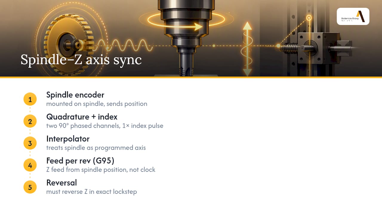
The controller’s interpolator then treats the spindle as if it were just another programmed axis. Instead of the Z axis following a time based feed rate, it follows the spindle’s actual position in real time, moving a fixed distance for every increment of spindle rotation. This is why feed per revolution mode (G95) is a prerequisite rather than a preference: it tells the controller to calculate Z axis feed directly from spindle position rather than from a clock, which is the entire mechanism that makes the thread pitch accurate regardless of small speed fluctuations during the cut.
Reversal is the hardest part of this loop to execute cleanly. At the bottom of the hole, the controller commands the spindle to decelerate, stop, and reverse direction, while the Z axis must reverse in exact lockstep. Any delay between the spindle’s actual reversal and the Z axis catching up shows up as thread damage right at the bottom of the hole, which is usually the first place a synchronisation problem becomes visible on an inspected part.
Why machine rigidity and control latency decide success or failure
Two machines running an identical program, identical tap, and identical material can produce very different rigid tapping results if their structural rigidity or control latency differs. Rigidity affects how much the spindle and column deflect under the axial and torsional load of tapping. A machine with more give in the spindle housing or column allows tiny position errors to creep in during the cut, and those errors show up directly as thread inconsistency because there’s no floating holder left to absorb them.
Control latency is the less visible half of the equation. Every controller takes some finite time to read the encoder signal, calculate the required Z axis position, and command the servo to move. On a well tuned modern control that lag is negligible. On an older or poorly tuned system, particularly at higher spindle speeds where the spindle covers more angular distance per millisecond, that lag becomes the dominant source of thread error.
This is exactly why very high speed small tap work, at several thousand RPM and above, sits at the edge of what many spindles can track and reverse accurately, regardless of how good the controller’s software is. Spindle inertia at that speed simply takes measurable time to reverse, and no amount of clever programming shortens that physical reality. It’s the reason reversing heads remain standard equipment for micro tapping work even on machines fully capable of rigid tapping everywhere else.
Keeping the spindle encoder calibrated for consistent tapping
An encoder that’s drifted out of calibration doesn’t usually fail outright. It degrades quietly, and rigid tapping is often the first operation on the machine to expose it, because tapping has zero tolerance for position error the way a roughing pass does.
Routine checks worth building into a maintenance schedule include verifying encoder mounting integrity (a loose coupling or worn belt on a belt driven encoder introduces exactly the kind of lag that shows up as thread depth variation), checking for contamination on optical encoder discs where coolant mist or swarm dust can affect signal quality, and running the machine builder’s spindle orientation and positioning diagnostic periodically rather than only when a fault appears.
Thermal drift is worth watching too. A spindle that runs hot over a long production shift can shift slightly in its housing, and on some machines that’s enough to introduce a small but measurable synchronisation error by the end of the day that wasn’t there at startup. Comparing first article inspection results from the start and end of a long shift is a simple way to catch this before it becomes a batch of out of tolerance parts.
None of this replaces the manufacturer’s own calibration procedure, but a shop that treats the encoder as maintenance-free equipment is a shop that eventually gets an unexplained run of bad threads with no obvious cause.
How material choice changes your tapping parameters
Rigid tapping parameters that work perfectly in aluminium can snap a tap in stainless, and the difference comes down to how the material behaves under torque and how its chips form.
Aluminium and other soft, gummy materials tend to produce long stringy chips that pack into blind holes readily, so peck parameters and through tool coolant matter more here than raw spindle speed. Mild steel sits in a comfortable middle ground for most standard taps and feed calculations, and it’s usually where shops validate a new rigid tapping setup before extending it to harder jobs. Stainless steel and other work hardening alloys punish hesitation: any dwell or inconsistency in feed lets the material work harden locally, increasing cutting torque and raising the risk of tap breakage on the very next pass. Cast iron produces abrasive, gritty chips that accelerate tap wear regardless of how good the synchronisation is, making tap coating and flute geometry the bigger lever there.
Tap life scales with these material differences more than with rigid tapping setup quality alone. A spiral point tap in aluminium might run thousands of holes before replacement. The same tap geometry in stainless could see wear in a fraction of that count. Matching tap coating (TiN, TiCN or similar) and flute style to the material is as much a part of rigid tapping success as getting the feed per revolution calculation right.
Rigid tapping on 5 axis and multi-operation machining centres
Adding rigid tapping to a multi axis program introduces one more coordinate transformation the controller has to manage correctly: the tap axis and the tool tip position need to align through the same kinematic model as every other tool in the program, even when the tapping operation happens on a tilted or rotated plane.
On a 5 axis machining centre, this usually means the tapping cycle runs after the controller has already applied tool centre point control to position the spindle normal to the work surface. The synchronisation between spindle rotation and Z axis feed still works exactly as it does on a 3 axis machine. What changes is that “Z axis” in the cycle now refers to the tool’s own axis in space, not the machine’s physical Z axis, and getting that transformation wrong is a common source of tapping errors on multi axis parts that never show up in 3 axis testing.
Production machining centres with auto pallet changers add a different consideration: rigid tapping cycles running across multiple pallets need consistent spindle warm up and encoder behaviour regardless of which pallet is loaded, since a cold spindle at the start of a shift can behave differently to a warmed one by mid shift. Machines like the MASS series 5 axis centres are built with the spindle rigidity and structural stiffness that multi axis tapping demands, which matters more once a program is running tapping operations across several tilted orientations in a single cycle rather than a single flat face.
What actually separates a good rigid tapping setup from a bad one
Most of the advice floating around workshops treats rigid tapping as a switch you flip: enable G84, set a feed, and the machine handles the rest. That’s true for a straightforward through hole in mild steel on a well maintained machine. It falls apart the moment you’re working blind holes, harder materials, or a machine with any drift in its spindle encoder response.
The single most underrated factor isn’t the program. It’s whether anyone has actually verified the machine’s synchronous tapping response with a real single hole test, at real production RPM, before trusting a full batch to it. Plenty of shops skip this because the canned cycle “worked” in a quick air cut, which tells you nothing about how the spindle behaves under actual cutting load.
The other misconception worth challenging is treating rigid holders and floating holders as a binary choice. The better framing is rigid tapping with the right amount of controlled flexure for the material and hole depth in front of you. Perfectly rigid isn’t always the goal. Predictable is.
If there’s one thing to prioritise first, it’s the machine’s spindle and encoder response, not the tap brand or the holder catalogue. No holder fixes a controller that lags behind the spindle.
Get equipment that holds synchronisation when it matters
Anderson Group Australia supplies CNC machinery, servicing and spare parts. Confirm the exact machine configuration, installation arrangements and available support with the team.

If your current machine struggles to hold thread depth consistently, or you’re speccing a new centre for production tapping work, Anderson’s metalwork CNC machinery range is built for manufacturers in automotive, aerospace, marine and general engineering who need tapping results that hold tolerance batch after batch. Browse the full CNC machinery range or get in touch to talk through spindle specification and encoder feedback options for your specific tapping requirements.