
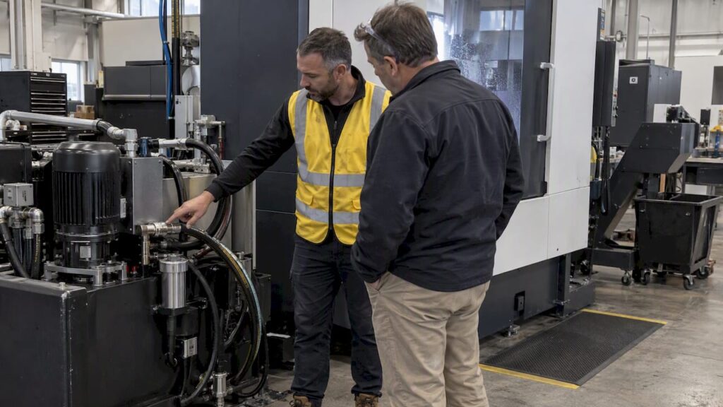
High pressure coolant (HPC) delivers cutting fluid at 70 to 80 bar for many metal-cutting applications, with some systems running to 150 bar for difficult chip control. Turning benefits from targeted, high-velocity jets that break chips at the cutting edge, while drilling and through-tool applications depend more on flow volume to clear swarf and carry heat away.
TL;DR:
- Maintaining 70 to 80 bar pressure effectively breaks chips and reduces tool temperatures, but higher pressures up to 150 bar may increase wear in some cases.
- Flow volume is critical for coolant delivery in drilling and through-tool applications, with typical requirements around 20 L/min per nozzle.
- Proper nozzle size and placement are essential, as smaller nozzles increase jet velocity but demand cleaner coolant to prevent blockage.
- System components like filters, tank capacity, and pressure sensors must be carefully matched to avoid pressure drops and ensure reliable coolant delivery.
- Managing mist and microbial risks requires enclosure, proper filtration, routine sump cleaning, and adherence to safety data sheet guidance.
Table of Contents
- Benefits and limitations of high pressure coolant
- Pressure versus flow: sizing a system for turning, drilling and multi-tool setups
- Tooling and nozzle considerations for precision coolant delivery
- Pump, filtration and tank spec checklist for high pressure coolant systems
- Health, mist control and microbiological risk management
- Maintenance, troubleshooting and common failure modes
- How Anderson supports customers specifying and integrating HPC-ready systems
- Request a quote or technical appraisal from Anderson Group Australia
- FAQ
- Sources
Benefits and limitations of high pressure coolant
Delivered as a narrow, high-velocity jet, HPC acts as a hydraulic wedge at the tool’s rake face, shortening the tool-chip contact length and improving chip breaking in turning operations. A peer-reviewed study testing supply pressures up to 300 bar and flows to 55 L/min found tool temperatures dropped by close to 25%, with tool wear reduced by as much as 50% in some trials. That same study found the effect was material- and condition-dependent: in certain combinations, higher pressure actually increased tool wear rather than reducing it.
The practical gains and trade-offs look like this:
- Cooling and lubrication: lower cutting-zone temperature can extend tool life, though results vary by material and tool grade.
- Chip control: targeted jets improve chip breaking in turning and swarf clearance in drilling.
- Surface finish: more consistent chip evacuation reduces re-cutting and scoring.
- Wear risk: some tool and workpiece combinations show increased wear at higher pressure, so pressure is not universally beneficial.
- Cycle time and automation: reliable chip evacuation supports unattended running, which is a common driver for adoption alongside tool life monitoring as part of a broader process data strategy.
Pressure versus flow: sizing a system for turning, drilling and multi-tool setups
Pressure and flow solve different problems. Pressure, multiplied by the delivery orifice area, determines jet velocity at the cutting edge, which is what breaks a chip in turning. Flow, measured in litres per minute, determines how much coolant reaches the tool to carry away heat and clear swarf, which matters more in drilling and through-tool work.
Sandvik Coromant’s guidance sets out typical bands: 70 to 80 bar suits many general turning and milling jobs, while pressures up to 150 bar are reserved for hard-to-break chips in tougher materials. As a working example, three 1 mm nozzles on a single turning position typically require a flow in the range of about 20 L/min, with total flow increasing with the number of simultaneous tool positions drawing coolant.
| Operation type | Typical pressure | Priority |
|---|---|---|
| General turning | 70 to 80 bar | Pressure for chip breaking |
| Hard-to-break chips | Up to 150 bar | Pressure, narrow jet |
| Drilling / through-tool | Lower pressure acceptable | Flow volume |
| Multi-tool simultaneous | Varies by position | Combined flow across outlets |
A variable-pressure pump lets one system cover both needs, but the pump’s rated flow at the actual operating pressure, not just its maximum pressure figure, is what should drive selection.
Tooling and nozzle considerations for precision coolant delivery
Through-tool drills and internal-channel toolholders deliver coolant directly to the cutting edge and generally outperform external piping, which struggles to maintain jet accuracy as the tool wears or the turret indexes. Plumbed quick-change holders reduce set-up variation because the coolant path is fixed and repeatable rather than re-aimed by hand each job.
Reducing nozzle diameter increases jet velocity for a given pressure, since orifice area and pressure together determine delivery force. Smaller nozzles concentrate flow but demand cleaner coolant to avoid blockage, which ties nozzle choice directly to filtration specification.
- Check toolholder and seal pressure ratings before retrofitting HPC to an existing turret or spindle.
- Verify quick-change plumbing is compatible with rotating tool dynamics, since spindle rotation changes pressure behaviour at the seal.
- Position nozzles to avoid chip traps and physical interference with tool changers or part fixtures.
Pro Tip: Confirm nozzle orifice area against pump flow before committing to a quote. An undersized nozzle on an oversized pump wastes pressure and starves the cut of volume.
Pump, filtration and tank spec checklist for high pressure coolant systems
A specification checklist should cover coolant concentration and type, tank capacity, target pressure and flow at the tool, the number of simultaneous outlets, filtration rating, pump control and integration with the CNC controller, in line with practical application guidance.
- Pump: confirm maximum pressure, rated flow at that pressure (not just peak flow), variable-pressure control range and safety relief valve settings.
- Filtration: specify filtration rating (commonly around 20 microns for HPC systems), dirt-holding capacity and whether filtration sits on the return or suction side.
- Tank: size capacity to the machine’s flow demand, include temperature control where sustained high-duty cycles are expected, and plan for easy sump access and a make-up water strategy.
- Controls: fit pressure sensors and alarms, integrate with PLC or M-code control for automatic pressure switching, and include interlocks that stop coolant delivery if pressure falls outside the set range.
Treating these as one integrated package rather than a pump bought in isolation avoids mismatches between what the pump can deliver and what the nozzles and filtration can actually use.
Health, mist control and microbiological risk management
Metalworking fluid aerosols and mist from high pressure delivery carry inhalation and skin exposure risks, and Australian workplace guidance recommends SDS-based risk assessment, enclosure, local exhaust ventilation, splash guards and settling delays before opening guards after a cycle.
- Base controls on the product’s safety data sheet, not general assumptions about coolant type.
- Enclose the cutting zone and fit dedicated mist extraction where aerosol generation is unavoidable.
- Schedule sump cleaning and monitor fluid condition rather than waiting for visible contamination.
- Use PPE appropriate to aerosol exposure during any manual intervention near running coolant.
High-pressure water and mist can generate aerosols that carry Legionella risk when contaminated, and jurisdictional codes of practice recommend commissioning flushes, scheduled disinfection and monitoring to manage this. Microbial proliferation risk rises when circulation stops and oil-water emulsions separate, so sumps should turn over regularly, with conductance or total dissolved solids monitored and biocide dosed per the supplier’s SDS.
Maintenance, troubleshooting and common failure modes
Daily and weekly checks keep an HPC system performing as specified rather than drifting into unreliable territory.
- Check pressure and flow at the tool, not just at the pump gauge, since line losses and worn nozzles reduce delivered pressure.
- Inspect nozzles for wear or blockage, since enlarged or clogged orifices change jet velocity even when pump output is unchanged.
- Monitor filter differential pressure to catch clogging before it starves flow to the tool.
- Investigate leaks, worn pump seals and blocked returns as the most common causes of pressure loss.
- Check water hardness and coolant total dissolved solids against the product’s technical data sheet before adding antifoam, since foaming is often a system compatibility issue rather than a coolant fault, as Sandvik’s turning guidance notes when comparing delivery methods.
When a fault persists past these checks, collecting pressure and flow readings at the tool, filter condition and recent coolant concentration readings gives a technician a useful starting point for diagnosis.
How Anderson supports customers specifying and integrating HPC-ready systems
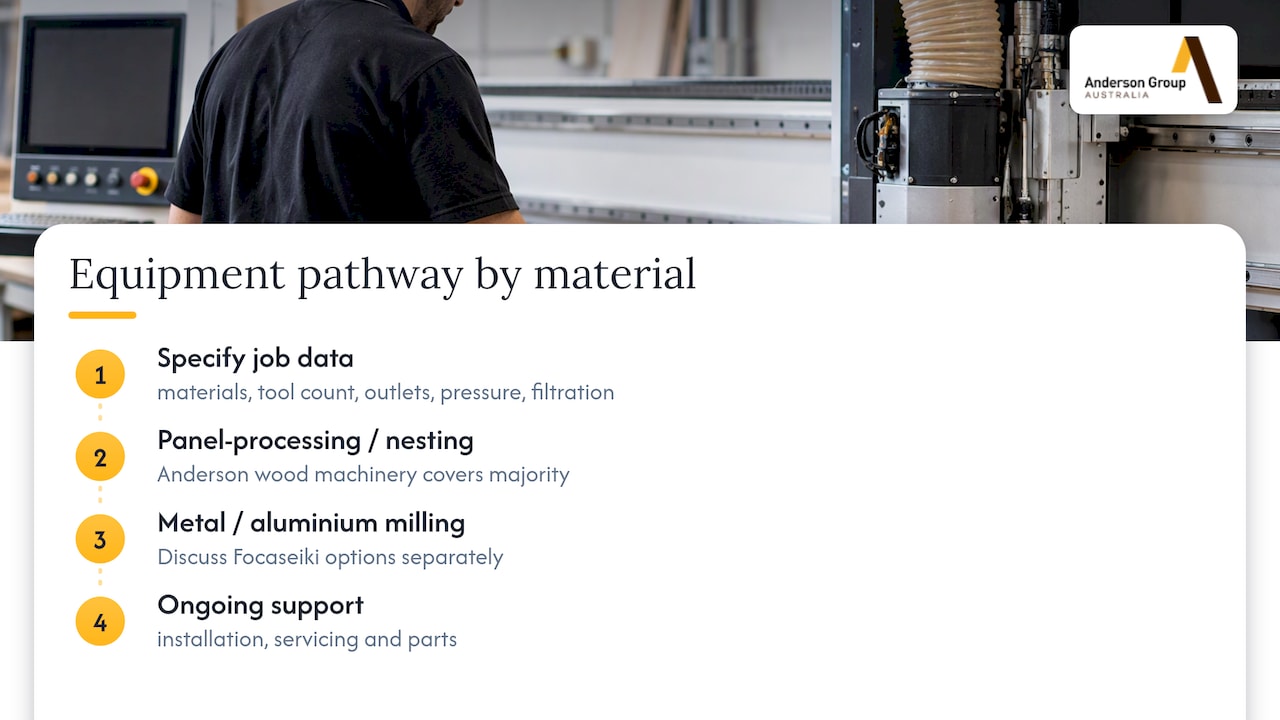
When discussing an HPC-capable machine package, we ask for the materials being cut, tool counts and whether simultaneous outlets are needed, target pressure and flow at the tool, and filtration requirements. That data lets us match the right machine range to the job rather than oversizing or undersizing the coolant system.
For metal or aluminium machining, review the metal machinery range and confirm whether the proposed machine supports the required high-pressure coolant configuration. For cabinet, joinery and furniture work, discuss dust extraction separately from liquid coolant requirements. Confirm installation, servicing and parts arrangements for the quoted machine.
Request a quote or technical appraisal from Anderson Group Australia
If you are assessing high-pressure coolant for a new or existing metal-machining process, record the required pressure and flow at the tool, filtration and tooling requirements. Discuss the exact configuration and coolant-system compatibility with Anderson Australia before selecting a machine range, and confirm the installation and service scope in the written proposal.

Request a site-specific appraisal through our machines page and we will talk through the coolant and tooling setup that fits your actual job, not a generic spec sheet.
FAQ
What is high pressure coolant?
High pressure coolant is cutting fluid delivered through the machine tool at pressures well above conventional flood coolant, often 70 to 80 bar for general metal cutting; confirm the selected machine’s pressure and flow. It is used to break chips in turning and to clear swarf and remove heat in drilling and through-tool operations.
What would cause high pressure in a coolant system?
Unusually high system pressure is most often caused by a blocked nozzle, a clogged filter, a closed or faulty valve downstream of the pump, or a pump relief valve set too high for the circuit. Checking pressure at the tool against the pump’s rated output is the fastest way to isolate where the restriction sits.
How much coolant pressure is normal?
Normal HPC pressure for general turning and milling sits around 70 to 80 bar, with pressures up to 150 bar reserved for materials that produce hard-to-break chips. Drilling and through-tool work often prioritise flow over peak pressure, so normal operating pressure depends on the specific job.
Does low coolant cause high pressure?
A low coolant level in the tank does not directly raise system pressure, since pressure is generated by the pump against downstream restriction, but a low level can cause the pump to cavitate or run dry, which damages seals and leads to erratic pressure readings. Checking tank level and make-up water supply is a standard step when troubleshooting unstable pressure.
Sources
- High pressure coolant — Sandvik Coromant
- Study on high-pressure coolant effects — MDPI
- Code of practice — Prevention and control of Legionnaires’ disease (WorkSafe WA)