
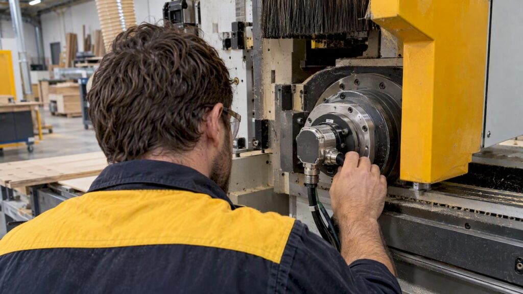
Use absolute encoders for CNC axes that need position retention after power loss and reliable multi-turn feedback, such as spindles, rotary tables and 4th/5th axes. Unlike incremental encoders, they produce a unique digital code for every shaft position, so the control knows exactly where each axis sits the moment power returns. That matters most where re-homing is costly or downtime cannot be tolerated.
TL;DR:
- Absolute encoders support multi-turn feedback and retain position after power loss, making them suitable for spindles, rotary tables, and axes where re-homing is costly or slow.
- They use a multi-bit digital code, often in Gray code format, with resolution specified in bits that determine steps per revolution, from single-turn to multi-turn configurations.
- Absolute encoders are more expensive and complex to install than incremental encoders, but are essential for axes where safety and downtime reduction outweigh cost concerns.
- Proper wiring, protocol support, and environmental protection are critical for reliable operation in harsh workshop conditions, especially IP65-rated housings and shielded twisted pair cabling.
- During installation, verifying mechanical alignment, correct wiring, and performing speed tests are vital to ensure accurate, safe, and reliable CNC axis feedback.
Table of Contents
- 1. How absolute encoders work on a CNC machine
- 2. Absolute vs incremental encoders: practical trade-offs for CNC builders
- 3. Key specifications to pick for CNC axes
- 4. Interfaces, wiring and integration: SSI, BiSS and common protocols
- 5. Mounting, protection and environmental considerations for shop floors
- 6. Safety, WHS and commissioning best practice for encoder-based monitoring
- 7. Installation and commissioning checklist for CNC builders
- How Anderson Group Australia can help with machines, parts and service
- FAQ
- Sources
- Key references and primary sources
1. How absolute encoders work on a CNC machine
An absolute encoder outputs a multi-bit digital word that represents shaft position directly, rather than a stream of pulses that must be counted from a reference point. Many devices use Gray code internally, which changes only one bit per step and reduces read errors at transition points, before converting to binary for the controller.
Single-turn absolute encoders measure position within one full rotation, 0 to 360 degrees, and repeat the same code every revolution. Multi-turn versions add a gear train or electronic counter that tracks how many full rotations have occurred, so the controller retains position across multiple turns of a leadscrew or rotary table, even through a power cycle.
Resolution on the datasheet, expressed in bits, sets how finely that single rotation is divided. An academic project report describing absolute encoder types notes a single-turn device with 8,192 steps per revolution, which resolves to roughly 0.005 degrees per step.
Practical points for specification:
- Single-turn encoders suit axes confined to one rotation, such as a tool-change carousel.
- Multi-turn encoders suit leadscrews, ball screws and rotary tables that travel many revolutions.
- Bit count on the datasheet converts directly to steps per revolution (2 raised to the bit count).
- Encoder counts feed the control loop as the raw position input before any gearing or scaling is applied.
2. Absolute vs incremental encoders: practical trade-offs for CNC builders
Both encoder families measure rotation, but they behave very differently once power drops or the machine restarts.
- Power-loss behaviour: an absolute encoder retains its position code without moving, while an incremental encoder loses count and the axis must re-home before the control trusts its position again.
- Bandwidth and control-loop response: incremental encoders often output simple pulse trains that some drives process marginally faster, though this gap narrows with modern digital absolute interfaces.
- Cost and complexity: multi-turn absolute encoders with sealed housings and digital interface electronics generally cost more than equivalent incremental units, reflecting the added gearing or battery-backed counting hardware.
- Axis assignment: reserve absolute encoders for spindles, rotary tables and 4th/5th axes where re-homing is slow or unsafe, and consider incremental encoders only where a fast, repeatable home cycle is already built into the machine’s routine.
3. Key specifications to pick for CNC axes
Datasheet numbers only matter once they are converted into the units a machinist actually works with: degrees, micrometres or arcseconds at the tool tip.
Resolution in bits sets the theoretical step size, but accuracy and repeatability are separate figures. Accuracy describes how close the encoder’s reported position is to the true position; repeatability describes how consistently it returns to the same reading. System-level factors, including gearbox backlash, coupling slop and mounting runout, often dominate the final error budget more than the encoder’s own resolution.
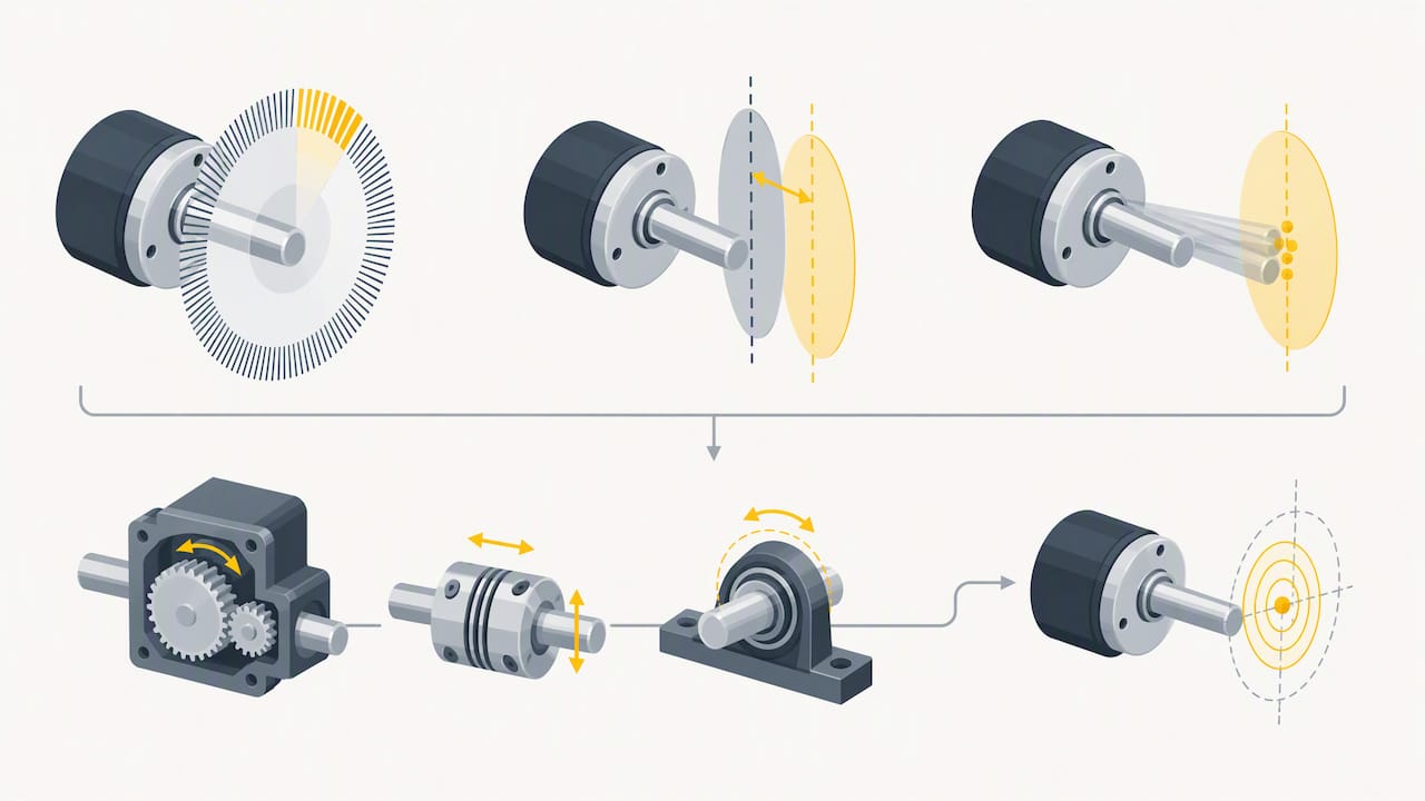
Update rate and signal latency affect how tightly a servo loop can track fast-moving axes. A high-resolution encoder that updates slowly can still introduce lag into a fast spindle or rotary loop, so update rate deserves equal attention to bit count.
Mechanical fit matters just as much: confirm shaft diameter, flange pattern and coupling type against the drive or axis before ordering, since a mismatched coupling introduces backlash that no amount of encoder resolution can correct.
Selection checklist:
- Convert bit resolution to arcseconds or micrometres at the actual working diameter before comparing models.
- Check accuracy and repeatability separately; they are not the same specification.
- Match update rate to the fastest axis speed the machine will run.
- Verify shaft size, flange and coupling compatibility against the actual mounting point.
Pro Tip: Specify the tolerance you need at the tool tip first, then work backwards to the encoder resolution and coupling accuracy required to achieve it, using a reference such as this guide to precision machining tolerances to frame the conversation with your control-system supplier.
4. Interfaces, wiring and integration: SSI, BiSS and common protocols
Most industrial absolute encoders on CNC machines communicate over SSI (Synchronous Serial Interface) or BiSS, both digital protocols built for transmitting position data reliably in electrically noisy workshop environments. A comparison of absolute encoder interfaces notes that modern high-precision encoders can support resolutions from 19 to 25 bits over these interfaces.
Wiring practice affects signal integrity as much as the protocol choice. The same comparison recommends differential signalling over RS-422, run on twisted shielded pair cabling with proper termination, to reduce electrical noise on SSI and BiSS runs.
Before procurement, confirm:
- The CNC drive or controller explicitly supports the encoder’s protocol version, not just “SSI-compatible” in general terms.
- Cable runs use shielded twisted pairs with the shield grounded at one end only, to avoid ground loops.
- Multi-axis installations follow a consistent addressing and topology pattern so troubleshooting one axis does not require re-learning the wiring scheme for another.
- Termination resistors match the manufacturer’s specification at both ends of long differential runs.
5. Mounting, protection and environmental considerations for shop floors
Dust, coolant and vibration are routine hazards on both woodworking and metalworking floors, and encoder housings need to be rated for them. Guidance on encoders for harsh environments recommends IP65 or higher ingress protection where dust or coolant exposure is constant, which covers most cabinetry and panel-processing shops as well as metal-cutting cells.
Hollow-shaft encoders mount directly onto a motor or spindle shaft and tolerate a small amount of misalignment, while shafted encoders need a flexible coupling to absorb runout; choosing the wrong style for the application is a common cause of premature bearing wear.
Key environmental checks:
- Confirm IP65+ rating for any encoder exposed to wood dust, swarf or coolant mist.
- Match hollow-shaft or shafted mounting style to the available space and expected misalignment.
- Check the encoder’s rated vibration and shock tolerance against the axis it will serve.
- Schedule periodic inspection as part of routine CNC preventive maintenance, since seal degradation is a leading cause of field failure.
6. Safety, WHS and commissioning best practice for encoder-based monitoring
An encoder’s position signal is not, by itself, a certified safety function. Under Australian WHS guidance, SafeWork SA’s safety alert on bypassing safety devices makes clear that employers must keep safety devices, including encoder-integrated monitoring and interlocks, correctly maintained and never bypassed, and must provide training on their correct operation.
Tampering with a safety interlock to work around a fault is a breach of WHS obligations, according to that same SafeWork SA guidance, and it removes the protection the device was installed to provide.
Commissioning steps worth documenting:
- Confirm certified presence-sensing devices and interlocks handle the actual safety function, with the encoder providing position feedback only.
- Record static and dynamic test results comparing encoder-derived position against an independent reference such as a dial indicator or laser measurement.
- Reference the AS/NZS 4024 safety standard when documenting machine-level safety compliance for the installation.
- Ensure operators and installers hold relevant competency, such as the national unit CPCCJN3002 Use computer-controlled machinery, which covers programming, loading, testing and measurement techniques for CNC equipment.
7. Installation and commissioning checklist for CNC builders
A structured commissioning sequence catches most encoder-related faults before they cost production time.
- Check mechanical alignment, shaft runout and coupling torque against the manufacturer’s tolerance before first power-up.
- Verify differential pair wiring, shield termination and ground connections, then confirm the protocol frame (SSI or BiSS) is being read correctly by the controller.
- Scale raw encoder counts to degrees or revolutions in the control software, then run the axis at working speed to confirm closed-loop tracking holds under load.
- Record functional safety checks and keep documentation on file, consistent with the WHS expectations around maintained interlocks.
Pro Tip: Run a slow-speed and a full-speed tracking test before handover. A coupling or wiring fault that passes a static check often only shows up once the axis is moving at production speed.
How Anderson Group Australia can help with machines, parts and service
We supply CNC machinery, spare parts and on-site servicing to manufacturers across the wood, metal and advanced materials sectors, including nesting and panel-processing machines like Genesis PLUS where reliable axis feedback matters most.

If you are specifying or troubleshooting encoder-equipped axes on a new or existing machine, we are glad to talk through your requirements or arrange a service visit. We do not offer subcontract cutting or finished-part manufacturing: our focus is machinery, parts and support for your own production. Browse our wood machinery range or get in touch to discuss your next machine or a parts and service enquiry.
FAQ
What are the downsides of absolute encoders?
Absolute encoders generally cost more than incremental equivalents, particularly multi-turn models with sealed housings and digital interface electronics. They can also introduce more wiring and protocol complexity during commissioning, since the controller must correctly interpret the SSI or BiSS data frame rather than a simple pulse count.
What does an absolute encoder do?
An absolute encoder outputs a unique digital code for every shaft position, so the controller always knows the exact position without needing to count pulses from a reference point. This position is retained even after a power loss, which is why these encoders suit axes where re-homing would be costly or slow.
Which is better, an absolute or incremental encoder?
Neither is universally better: the right choice depends on the axis. Absolute encoders suit spindles, rotary tables and 4th/5th axes where retained position after power loss matters, while incremental encoders can suit simpler axes with a fast, reliable homing routine already built in.
Why are absolute encoders so expensive?
Multi-turn absolute encoders need additional gearing or electronic counting hardware to track rotations beyond 360 degrees, plus sealed housings and digital interface electronics to transmit position data reliably. These added components, rather than the base sensing technology, largely drive the higher cost compared with incremental encoders.
Sources
- Comparison of absolute encoder interfaces: SSI, BiSS and CANopen
- SafeWork SA — Dangers of bypassing safety devices (safety alert)
- Training
- Academic project report describing absolute encoder types and SSI usage (Murdoch research portal)
Key references and primary sources
The technical and safety points above draw on manufacturer and research documentation on absolute encoder design, interface protocols and Australian WHS guidance.