
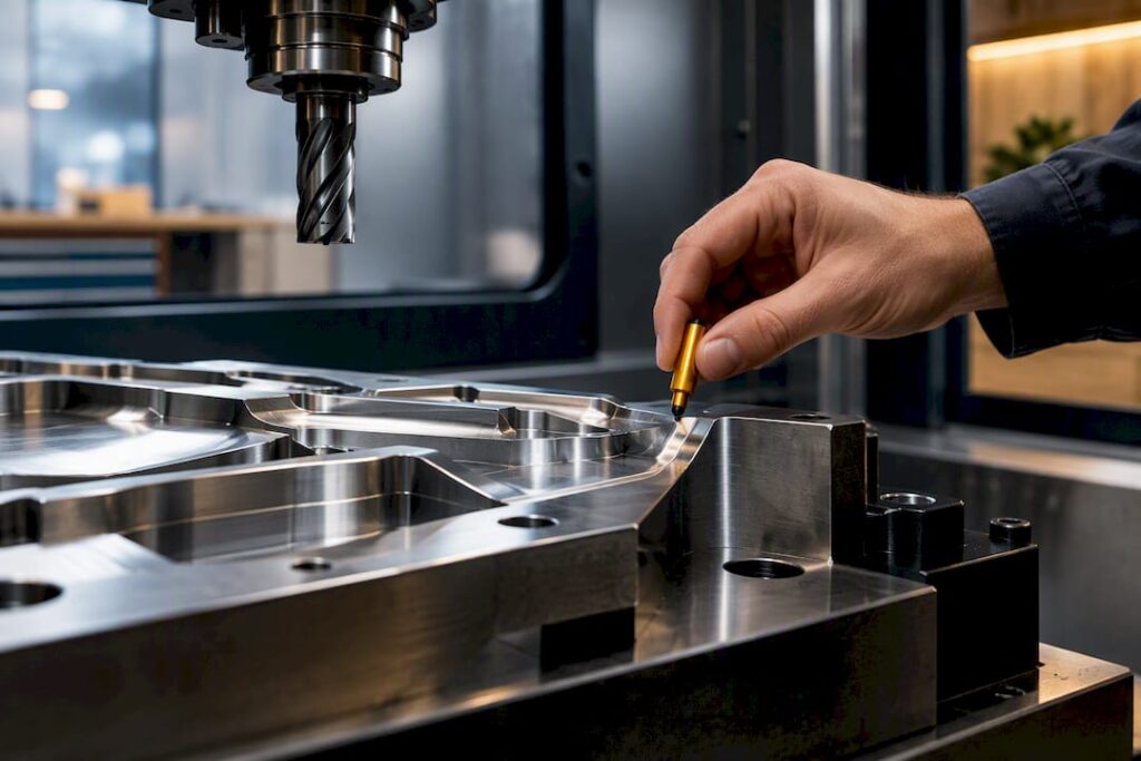
Success in automotive die machining means one thing: a die that holds its dimensions through its full production life and clears every trial acceptance criterion before it ships. Getting there depends on three controls, in order of importance. Datum continuity from roughing through heat treatment to final inspection prevents the tolerance drift that sinks most launches. Material and coating choice matched to the sheet grade and run length prevents premature wear. Structured trialling, with genuine time built into the schedule for correction, catches what specification alone never will. Some companies have spent decades supplying the machine platforms that make these three controls achievable on the shop floor.
TL;DR:
- Proper die material and coating selection depend on part size, draw severity, and expected volume, not on a single factor.
- Maintaining datum continuity through all machining and heat treatment stages is critical to prevent tolerance drift and ensure final accuracy.
- Machine capability should prioritize spindle torque, thermal stability, and probing features over just spindle speed or axis count for high-precision die work.
- Scheduled physical inspections based on cycle count are more reliable for managing tool wear than relying on preset tool-life estimates.
- For HPDC dies, verifying cooling channels, vents, and vacuum paths through dimensional inspection and simulation is essential for casting quality.
Table of Contents
- What is die machining, and what does the automotive workflow look like?
- Which die steel and coating actually suit your part?
- What machine setup does high-precision die work actually need?
- How do you monitor and manage tool wear before it costs you a die?
- What’s different about machining HPDC dies?
- Why does datum strategy make or break your inspection results?
- How do you shorten total launch time, not just cycle time?
- Anderson perspective: specifying machinery and support for reliable die manufacture
- Get the right machine platform for your die program
- Sources
- FAQ
What is die machining, and what does the automotive workflow look like?
Automotive die machining covers the manufacture of stamping dies, high pressure die casting (HPDC) dies, moulds, punches and related inserts, using milling, grinding, wire EDM and precision measurement to hold cavity and profile tolerances. The national competency standard for cavity die manufacture treats stamping dies and HPDC dies as distinct disciplines, because their materials, thermal loads and validation methods diverge sharply. A stamping die lives or dies on sliding wear against sheet steel. An HPDC die lives or dies on thermal cycling against molten aluminium.
The workflow that connects specification to a released, production-ready die follows a set sequence, laid out in national tooling development guidance:
- Interpret the specification and confirm part geometry, tolerances and volume.
- Establish and record datums before any roughing begins.
- Select and, where needed, test the die material against the intended sheet or alloy.
- Rough machine to remove bulk stock efficiently.
- Stress relieve or heat treat to lock in hardness and dimensional stability.
- Finish machine to final cavity and profile tolerances.
- Assemble the die set and inspect against datums.
- Run trials, measure results and correct.
- Release to production.
The design package handed to the machinist needs to include CAD models, assembly drawings, material and heat treatment callouts, critical tolerances, and explicit trial acceptance criteria. Skip any of these and the trial phase turns into guesswork. Schedules also need a genuine tryout window. Treating trial time as a buffer rather than a planned phase is one of the most common reasons launches slip.
Which die steel and coating actually suit your part?
There’s no single best die material. Australian steel industry guidance is blunt about this: the right choice depends on part size, draw severity and production quantity together, not any one factor in isolation.
- Tool steels (D2, H13, S7) suit moderate-volume stamping dies where toughness and machinability matter more than absolute wear life.
- Cast irons work for low-stress die bodies and structural components where cost outweighs surface durability.
- Carbide inserts earn their premium on high-volume progressive dies cutting abrasive high-strength steel.
- Nitrided or coated surfaces (TiN, CrN, DLC) extend life on dies running advanced high-strength steel or aluminium, where galling and adhesive wear dominate.
Match the choice to sheet grade, thickness, sliding distance and expected run length, then set inspection intervals rather than trusting a nominal tool-life figure. Tool wear research from Monash University found wear prediction genuinely difficult because contact conditions shift with material pairing and geometry, which is exactly why scheduled physical checks beat a calendar guess.
Pro Tip: Log wear measurements against cycle counts from day one, not once you notice a problem. A wear curve you can compare against history is worth more than any single inspection reading.

What machine setup does high-precision die work actually need?
Die envelope decides the machine, not the other way round. Large stamping die bodies and long HPDC die halves usually call for double-column machining centres, which offer the bridge stiffness and table size to remove mass without chatter. Complex cavity work with undercuts, draft angles and multi-face features needs 5-axis vertical machining, which cuts the number of setups and preserves datum accuracy between operations.
A few machine specifications matter more than manufacturers often admit up front:
- Spindle torque and axis stiffness, which determine whether you can rough hardened die steel without deflection.
- Thermal stability across the machine structure, since a die held to microns can’t tolerate frame drift over an eight-hour cut.
- Probing capability, which lets you confirm datum position in-cycle rather than after the part comes off the table.
- Chip evacuation, covered in detail in Anderson’s guide to chip management for aluminium work, which becomes critical on deep-pocket HPDC dies where trapped chips ruin finish.
For production handoff, pallet-equipped systems reduce the dead time between operations that eats into launch schedules. Read more on machine selection specifics in Anderson’s automotive CNC machining guide.
How do you monitor and manage tool wear before it costs you a die?
Stamping dies wear through adhesive and abrasive mechanisms that accelerate sharply with high-strength steel and thin or degraded lubricant films. HPDC dies wear differently, through thermal fatigue cracking from repeated cycling against molten metal.
- Set fixed inspection checkpoints for wear radii on cutting edges, guide pin and bushing alignment, and clearance between punch and die.
- Schedule these checks by cycle count, not by calendar date, since wear tracks usage, not time.
- Flag any measurable radius growth or clearance shift against your logged baseline immediately, rather than waiting for a visible defect on the part.
- Decide in advance the rules for recoating versus full remanufacture. A worn nitrided surface can often be stripped and recoated; a cracked or deformed cavity usually can’t.
- Replace rather than repair once cumulative correction cost approaches the price of a new insert or component.
Contact conditions vary enough between jobs that a fixed tool-life number is rarely reliable on its own, which is why the Monash wear study argues for measurement-based scheduling over nominal estimates.
What’s different about machining HPDC dies?
HPDC dies carry design features stamping dies don’t: cooling channels, vents, vacuum paths, gates and overflows. Machining these features to spec isn’t optional finishing work; it’s the difference between a die that fills cleanly and one that produces porous, rejected castings.
- Preserve cooling channel geometry exactly as designed. A channel machined even slightly off-profile changes local solidification rate and shifts porosity to a new location.
- Verify vents and overflows against simulation output, not just the drawing, since research on HPDC defects identifies air entrainment and unstable fill fronts as central causes of structural casting failure.
- Validate with a combination of dimensional inspection and casting simulation. Surface finish alone tells you nothing about how metal actually fills the cavity.
- Where vacuum assistance is specified, confirm the vacuum path is fully sealed at machining tolerance, not just visually clear.
- Monitor real-time process parameters on trial shots. Emerging gigacasting work shows porosity below 0.5% is achievable in structural castings, but only with tight thermal management and vacuum control working together, not any single feature in isolation.
Why does datum strategy make or break your inspection results?
A die that measures out of tolerance after heat treatment is frequently a datum problem, not a machining problem. Precision tooling competency guidance requires datums to be established and locked before roughing starts, then preserved through every subsequent operation, including the thermal distortion that comes with heat treatment.
- Fix datum features early and reference every later operation, including finish machining and final inspection, back to those same points.
- Re-establish datum reference after heat treatment rather than assuming stress relief left geometry untouched.
- Use CMM measurement for critical cavity and profile dimensions, and 3D scanning for cooling channels, vents and other features a probe can’t reach cleanly.
- Design the trial itself to generate usable data: measure specific features against acceptance criteria, not just “does the part look right.”
Pro Tip: Treat your first trial shot as a diagnostic tool, not a pass/fail test. The measurement data from a failed trial is often more valuable than a lucky first pass, because it tells you exactly where the next correction needs to go.
How do you shorten total launch time, not just cycle time?
Chasing the fastest possible spindle cycle is a trap. Mazda’s die-manufacturing work found that improving machining accuracy through mechanism analysis and cutting-condition optimisation cut the polishing burden downstream, which shortened total launch time more than any cycle-time gain could.
- Machine to a surface quality that reduces hand-polishing hours, even if the cut itself takes slightly longer.
- Build inspection capacity and spare tooling into the launch plan, so a failed trial doesn’t stall the whole schedule.
- Schedule dedicated correction slots between trials rather than squeezing fixes into whatever time is left.
- Require cross-functional sign-off (design, process, quality) before release, not just a single engineer’s approval.
- Track first-article conformance rate, time-to-release and rework hours per launch as your real KPIs, not spindle utilisation.
Anderson perspective: specifying machinery and support for reliable die manufacture
We’ve supplied high-precision CNC equipment since 1972, and the pattern we see repeated across automotive projects is buyers specifying spindle speed and axis count first, then discovering too late that thermal stability and probing accuracy were the real limiting factors on their die tolerances. Machine selection for die work isn’t a features checklist. It’s a match between die envelope, expected tool loads and inspection handoff requirements.
Our view: involve your machine supplier during design for manufacturability, not after the die design is frozen. Fixture strategy and commissioning support decided early prevent the rework that eats launch schedules. A supplier who understands furniture, aerospace and automotive machining demands can flag a stiffness or thermal problem before it becomes a scrapped die.
— Anderson
Get the right machine platform for your die program
Most engineers evaluating die machining capacity end up choosing between building in-house capability or outsourcing to a job shop, and both routes have real limits: outsourcing means queueing behind someone else’s schedule, and building in-house without the right platform means retrofitting fixes after your first few dies come out of tolerance. Anderson Group Australia gives you a third path: production machining centres built for die envelope work, backed by decades of CNC manufacturing experience across metalwork applications since 1972.

Our range covers vertical machining centres for standard cavity work, 5-axis platforms for complex multi-face die features, and double-column centres for large stamping and HPDC die bodies. Beyond the machine itself, we support commissioning, fixturing advice, spares and ongoing maintenance, the parts of a die program that determine whether your second and third launch go faster than your first. If you’re specifying a machine platform for an upcoming die program, talk to our team about your die envelope and tolerance requirements before you lock in a spec.
Sources
- National Training Register — MEM18097A Manufacture cavity dies
- Monash University — tool wear study (Pereira 2010)
- Mazda technical case — machining accuracy reduces polishing (2026)
FAQ
What is die machining in automotive manufacturing?
Die machining is the process of cutting, grinding and finishing tool steel or cast iron to produce stamping dies, HPDC dies, moulds and punches used to form automotive components. It combines milling, EDM, wire cutting and precision measurement, and the national competency standard for cavity die manufacture treats stamping and HPDC die work as separate disciplines because their thermal loads differ.
How long should a die trial phase take?
There’s no fixed universal duration, since it depends on part complexity and how many correction cycles the trial data demands. What matters is building genuine tryout and correction capacity into the schedule up front, a requirement set out in national tooling development guidance, rather than treating trial time as a buffer to compress when the schedule tightens.
What causes premature die wear?
Premature wear typically comes from a mismatch between die material or coating and the sheet grade, contact pressure or production volume it faces. Wear research from Monash University found that contact conditions vary enough between jobs that prediction is genuinely difficult, which is why scheduled physical inspection outperforms relying on a nominal tool-life figure alone.
Why do HPDC dies need different validation than stamping dies?
HPDC dies carry cooling channels, vents, gates and vacuum paths that directly affect metal fill and porosity, features stamping dies don’t have. Research on HPDC defects identifies air entrainment and unstable fill fronts as major failure causes, so validation needs casting simulation and trial castings alongside dimensional inspection.
What machine features matter most for die machining accuracy?
Spindle torque, axis stiffness and thermal stability determine whether a machine can hold cavity tolerances through a long roughing or finishing cut. Anderson Group Australia’s 5-axis and double-column platforms are built around these same priorities, alongside probing capability and chip evacuation for deep-pocket die geometries.