
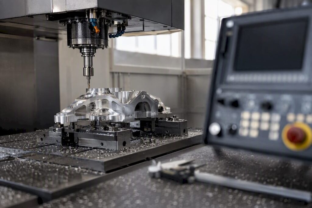
Automotive CNC machining is the use of computer-controlled milling, turning, grinding and EDM equipment to cut metal, plastic or composite stock into finished or near-finished vehicle components to tolerances often tighter than ±0.025 mm. For manufacturing engineers and procurement specialists, the verdict is straightforward: CNC remains the default choice for safety-critical, low-to-mid volume, or geometrically complex automotive parts, but the process is only as good as the supplier’s documented quality system behind it.
Before you send an RFQ, run three checks. First, confirm the tolerance class the drawing actually requires. Second, verify the supplier’s IATF 16949 certification status rather than taking ISO 9001 alone as sufficient. Third, ask what metrology equipment backs their inspection reports, not just what machines sit on their floor.
-
Tolerance class: match the drawing callout to a shop’s demonstrated CMM capability, not their marketing copy.
-
IATF 16949 status: mandatory baseline for OEM and Tier 1 supply, not a nice-to-have certificate.
-
Required metrology: in-process probing and SPC data separate real capability from a lucky sample part.
Quick fact: IATF 16949 extends ISO 9001 with automotive-specific demands, including APQP, PPAP and FMEA documentation, and most OEMs and Tier 1s will not onboard a supplier without it.
Key Takeaways
Automotive CNC machining succeeds when tight tolerance capability, documented IATF 16949 process control, and the right machine architecture are matched to the specific part, not bought as a generic package.
| Point | Details |
|---|---|
| Verify certification, not claims | Confirm current IATF 16949 status directly rather than accepting a supplier’s word or an expired logo. |
| Match tolerance to function | Specify tolerance bands the part actually needs; over-specifying inflates cost without adding safety margin. |
| Multi-axis reduces error | 5-axis machining cuts complex automotive geometries in one setup, avoiding cumulative fixture error. |
| Request process evidence | Ask for sample CMM reports and SPC data from real production runs before committing to a supplier. |
| Anderson maps capability to need | Anderson’s 5-axis, APC and large-format machining centres address the setup, throughput and tolerance demands this guide outlines. |
Table of Contents
-
What is automotive CNC machining and which processes does it cover?
-
How does multi-axis machining and automation improve automotive part quality?
-
How does CNC support prototyping through to full production?
-
What actually separates a capable shop from a certified one?
What is automotive CNC machining and which processes does it cover?
Automotive CNC machining refers to subtractive manufacturing processes, driven by digital toolpaths, that remove material from a metal, plastic, or composite billet to produce a finished automotive component. It sits apart from casting, forging and moulding because nothing is poured or pressed into shape; a cutting tool physically removes stock until the part matches the CAD model.
Engineers will see several core processes named on drawings and RFQs:
-
Milling cuts flat faces, pockets, slots and contoured surfaces, and is the workhorse for brackets, housings and manifolds.
-
Turning rotates the workpiece against a fixed tool, ideal for shafts, axles and cylindrical components.
-
Mill-turn combines both on a single machine, cutting setups for complex shaft-like parts with off-axis features.
-
EDM (electrical discharge machining) erodes hardened tool steel and exotic alloys electrically, used where conventional cutting can’t reach hardness or cavity geometry.
-
Grinding finishes hardened surfaces to fine tolerances and low surface roughness after primary machining.
-
Boring enlarges and finishes existing holes to precise diameter and roundness, critical for cylinder bores and bearing bores.
A typical workflow moves from raw billet through roughing (bulk material removal), semi-finishing, heat treatment if the alloy requires it, finish machining to final tolerance, and then a metrology check before the part ever leaves the shop floor. Skipping a step in that sequence is usually where dimensional drift creeps in.
Why does CNC machining matter for automotive precision?
Precision and repeatability are the two qualities that make CNC non-negotiable for safety-critical automotive parts. A brake calliper or connecting rod that’s out of tolerance by a fraction of a millimetre doesn’t just fail a quality check. It can cause premature wear or catastrophic component failure once the vehicle is on the road, which is why repeatability across thousands of cycles matters as much as hitting the number once.
CNC also brings flexibility that casting and moulding can’t match at low-to-mid volumes. A design change on a die-cast part means a new die; a design change on a CNC program means editing a toolpath. That difference is what makes CNC the default for prototyping, low-volume specialty vehicles, and any programme still iterating on geometry.
-
Precision: tolerance classes from general ±0.127 mm down to ±0.025 mm or tighter for critical bores, verified against a documented CMM report.
-
Repeatability: the same program produces the same part on run 1 and run 10,000, provided tool wear and thermal drift are actively managed.
-
Flexibility: geometry changes without new tooling investment, which matters heavily during vehicle development cycles.
-
Speed: shorter lead times from CAD to cut metal than any process requiring hard tooling.
CNC machining is used extensively across engine, transmission, suspension, braking and EV battery components today, and that spread across nearly every vehicle subsystem is precisely why supplier selection carries so much weight.
Pro Tip: Don’t specify tighter tolerances than the function requires. Every step down in tolerance class adds inspection time, slower cycle times, and often a different machine class altogether. A ±0.05 mm bracket doesn’t need ±0.01 mm capability, and asking for it just inflates your quote.
Which automotive parts are typically CNC machined?
Mapping CNC capability to real parts is more useful than a generic capability list, because tolerance and material requirements shift dramatically by vehicle subsystem.
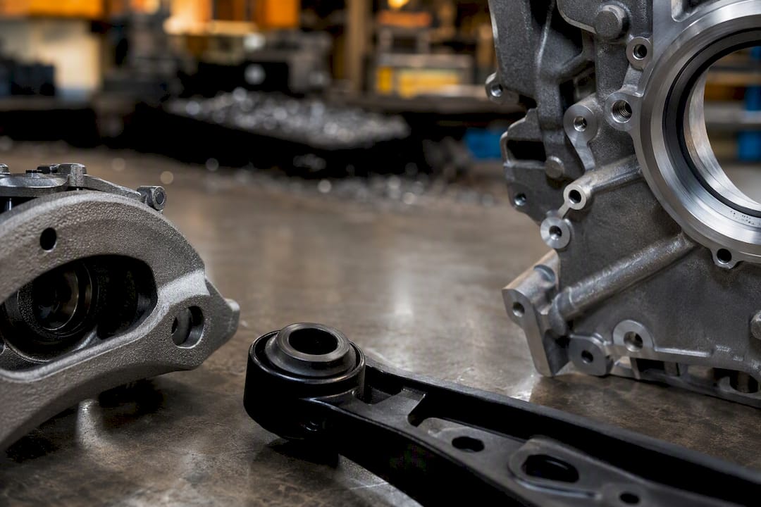
Engine components include cylinder heads, engine blocks, camshafts and crankshafts, usually machined from aluminium alloy or cast iron, with cylinder bores commonly held to tolerances as tight as ±0.025 mm given how directly bore geometry affects compression and oil control.
Transmission parts cover gear housings, shafts and synchroniser components, frequently in alloy steel, where gear-mesh surfaces demand both dimensional accuracy and a controlled surface finish to manage noise and wear.
Braking system parts include callipers, rotors and master cylinder bodies, typically cast iron or aluminium, where bore concentricity and surface finish directly affect pedal feel and stopping consistency.
Suspension components span control arms, knuckles and steering components, often in forged or billet aluminium and steel, where fatigue life depends heavily on surface finish quality after machining.
EV powertrain parts are the fastest-growing category: battery trays, motor housings, cold plates and copper busbars, often in thin-walled aluminium or copper, where combined mechanical and thermal tolerancing changes fixturing strategy entirely.
Interior and exterior trim covers switch housings, trim brackets and lighting components, frequently in engineering plastics or aluminium, generally at looser tolerance bands but with cosmetic surface-finish demands.
Parts with compound curves, undercuts, or features on multiple faces (a battery tray with sealed edges and mounting bosses, for instance) generally need 5-axis or multi-operation machining to hit these numbers in a single setup rather than stacking tolerance errors across multiple fixture changes. Cylinder bores, calliper bores and gear housings almost always need post-machining processes: honing, grinding or heat treatment before the part is considered finished. As one industry source puts it, tolerances can vary from loose to tight values depending on the criticality of the feature depending on the criticality of the feature, and that spread is exactly why a single supplier rarely quotes competitively across every part on a vehicle’s BOM.
How does multi-axis machining and automation improve automotive part quality?
Machine architecture and software determine how consistently a shop hits the tolerances above, and this is where equipment specification decisions really pay off or cost you.
Multi-axis machining centres, particularly 5-axis platforms, cut complex geometries in one setup instead of three or four. Every re-fixturing introduces positional error, so a battery enclosure or turbine housing with features on five faces benefits enormously from a machine that reaches all of them without moving the part. Anderson’s AXXIOM 5-axis series is built around exactly this problem: reducing setups on complex automotive castings and billets to cut cumulative error out of the process.
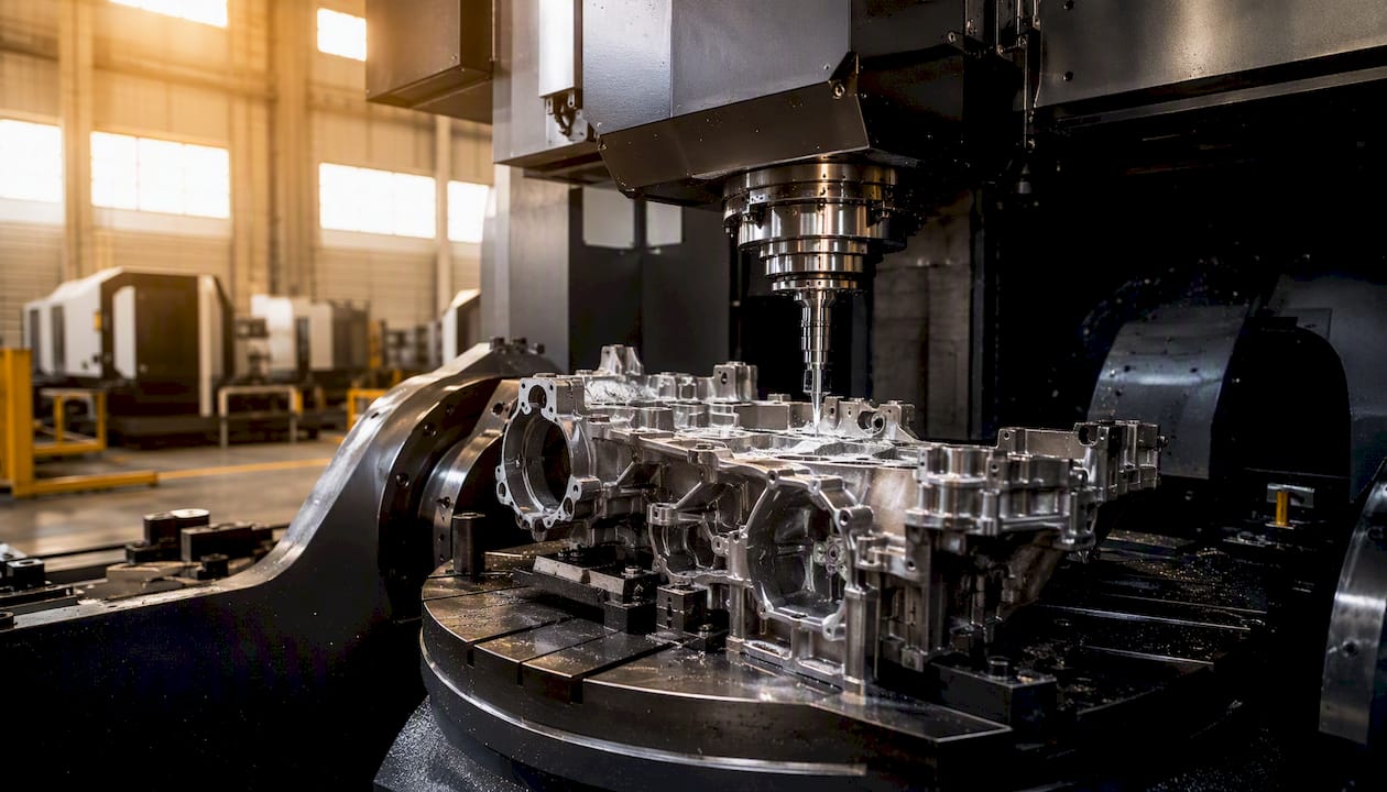
CAM software is just as decisive as the machine itself. Complex automotive geometries, thin walls, deep pockets, and blended surfaces need toolpath strategies that manage tool engagement and chip load automatically, because a hand-programmed path on a modern part invites gouging or premature tool wear. Pairing high-speed multi-axis hardware with CAM-driven toolpath optimisation is now considered standard practice on serious automotive programmes, not an optional upgrade.
Automation compounds these gains at production scale:
-
Robotic loading removes manual handling variance and keeps spindles cutting instead of waiting.
-
Auto pallet changers (APCs) let a machine finish one part while the next is loaded, lifting throughput without adding floor space.
-
In-process probing checks dimensions mid-cycle and corrects for tool wear before a part drifts out of spec, rather than catching it after the fact at final inspection.
Pro Tip: Always validate a CAM program on the actual target machine, not just in simulation. Post-processor mismatches between CAM software and machine controllers are a common, avoidable cause of scrapped first parts, and a five-minute dry run catches most of them before the spindle ever touches material.
What materials, tolerances and finishes should you specify?
Material choice, tolerance band and finish requirement together determine which shops can realistically quote your part, and getting any one of the three wrong inflates cost without adding function.
Aluminium alloys (6061, 7075, and cast grades like A356) dominate automotive machining for their strength-to-weight ratio, particularly in EV enclosures and suspension components. Steel and alloy steel grades cover gears, shafts and structural brackets where fatigue strength matters more than mass. Stainless steel appears in exhaust and fastener applications resistant to corrosion. Titanium shows up in performance and motorsport-adjacent components where weight savings justify the machining cost premium. Copper alloys are increasingly specified for EV busbars and thermal management parts. Engineering plastics and composites round out interior trim and lightweight bracket applications.
Anything tighter than roughly ±0.025 mm generally triggers climate-controlled inspection, because ambient temperature swings alone can move a part outside tolerance during measurement.
Surface finish is a separate specification from tolerance, and it’s easy to conflate the two. Grinding and honing refine functional surfaces like bores and bearing seats. Anodising adds corrosion resistance and colour to aluminium parts without meaningfully changing dimensions. Coatings, whether for wear resistance or cosmetic appearance, add both cost and lead time, so they need to be specified deliberately rather than defaulted to.
Pro Tip: Separate functional finish requirements from decorative ones on your drawing. A bore that needs a specific Ra value for sealing performance is a different spec, and a different cost line, from a visible bracket that just needs to look clean. Bundling them into one blanket finish callout is a common way procurement overpays.
How does CNC support prototyping through to full production?
The path from a one-off prototype to a validated production run follows a fairly consistent sequence, and knowing where the checkpoints sit helps you plan realistic schedules.
-
Prototype from billet. A single part or small batch machined directly from solid stock, skipping tooling investment entirely, to validate form, fit and function early.
-
Design iteration. Feedback from prototype testing feeds back into the CAD model; because no tooling exists yet, changes are just a program edit.
-
Pilot run. A small batch, often 10 to 50 units, run on production-representative tooling and fixturing to validate the process itself, not just the part.
-
Production and PPAP submission. Full-rate production begins alongside submission of first-article inspection reports and PPAP documentation to the customer for sign-off.
Billet prototyping typically turns around in days rather than weeks, since there’s no tooling lead time to absorb. Full production ramp, including PPAP submission and customer approval, more commonly runs into several weeks depending on part complexity and the number of sample parts required for statistical validation.
CNC increasingly plays a second role in this chain: finishing additively manufactured parts. Printed prototypes and even some production components often need secondary CNC machining to hit sealing surfaces or final tolerances that 3D printing alone can’t reliably deliver. This isn’t a rare exception; it’s becoming standard practice on hybrid workflows combining additive speed with subtractive precision.
Pro Tip: If you’re prototyping a cosmetic or optical part, ask your supplier about specialised finishing techniques, cryogenic cooling and diamond polishing for acrylic light pipes is one example that can get a prototype to near-production visual fidelity before you commit to tooling.
When is CNC machining not the right choice?
CNC machining loses its economic edge at very high production volumes, where the per-part cycle time and material waste from subtractive cutting can’t compete with die-casting or injection moulding once tooling costs are amortised across hundreds of thousands of units.
-
Cost at high volume: tooling-based processes overtake CNC economically once volumes climb into the hundreds of thousands per year.
-
Material waste: subtractive machining generates swarf, some of which is recyclable, but it’s still material paid for and then cut away.
-
Cycle time on complex parts: intricate geometries can mean long single-part cycle times compared to a die-casting shot measured in seconds.
-
Fixture and setup overhead: complex parts needing multiple fixture changes add non-cutting time that doesn’t scale well at volume.
Casting, forging or high-volume moulding generally win once a part design is frozen and volume is confirmed above roughly 100,000 units a year. Procurement red flag: if a quote request has no tolerance callouts at all on a complex geometry, that’s usually a sign the job hasn’t been engineered for CNC yet, and the RFQ needs to go back to design before it goes out to shops.
How do you choose CNC equipment or a machining supplier?
Selecting the right machine or supplier for an automotive programme comes down to matching documented capability against your part’s actual requirements, not against a shop’s sales pitch.
Machine specification checklist:
-
Number of axes and whether 5-axis capability is needed for your geometry.
-
Spindle power and speed range matched to your material (aluminium and titanium demand very different spindle characteristics).
-
Toolchanger capacity for complex parts requiring many operations without manual intervention.
-
Work envelope size relative to your largest component, oversized parts on an undersized machine is a common quoting mistake.
-
Automatic pallet changer (APC) or robotic loading if throughput matters more than one-off flexibility.
Supplier capability checklist:
-
Current IATF 16949 certification, not an “in progress” status.
-
An in-house metrology suite: CMM, surface roughness testing, and the ability to produce a report on demand.
-
Demonstrated SPC (statistical process control) practice, not just a claim of quality.
-
Prior first-article inspection (FAI) and PPAP submission experience with automotive customers.
-
Willingness to share sample CMM reports from comparable past work before you commit.
Red flags in a quote are usually specific and spottable. Watch for missing material traceability documentation, no mention of metrology equipment beyond “we check parts,” and vague tolerance commitments that dodge a specific number. The simplest test: ask for FAI or CMM data on a sample part before placing the order. A supplier confident in their process will have this ready within days; one that stalls or hedges is telling you something.
-
Confirm certification status directly with the supplier’s IATF 16949 auditor, not just a logo on their website.
-
Request a sample CMM report on a part with comparable tolerance requirements to yours.
-
Ask specifically how tool wear and thermal drift are monitored during long production runs.
If you’re weighing machine families for in-house production rather than outsourcing, Anderson’s CNC machinery range spans entry-level three-axis centres through enclosed 5-axis platforms, worth reviewing against the axis, spindle and automation criteria above.
What quality standards do automotive customers expect?
IATF 16949 is the standard nearly every OEM and Tier 1 customer requires before they’ll place a purchase order, and it exists precisely because ISO 9001 alone doesn’t address automotive-specific risk. ISO 9001 covers general quality management; IATF 16949 layers on requirements for advanced product quality planning, failure mode analysis, and statistical process control specific to automotive supply chains.
Expect to produce, or be asked for, these documents during supplier qualification:
-
APQP (Advanced Product Quality Planning): the roadmap for how a part moves from design to validated production.
-
PPAP (Production Part Approval Process), levels 1 through 5 depending on part criticality and customer requirement.
-
PFMEA (Process Failure Mode and Effects Analysis): documented risk assessment on how the process could fail and what controls prevent it.
-
MSA (Measurement Systems Analysis): proof that your inspection equipment itself is capable of measuring what it claims to measure.
-
SPC records: ongoing statistical evidence that the process stays in control over time, not just on the day of first-article inspection.
Achieving certification requires shops to produce evidence that tool wear and process drift are detected and corrected before out-of-spec parts leave the building, which is a meaningfully higher bar than simply owning capable machines.
What trends are shaping automotive CNC machining?
EV programmes are reshaping what “typical” automotive machining looks like. Thin-walled aluminium battery enclosures, liquid cold plates with internal thermal channels, and precision copper busbars all demand combined mechanical and thermal tolerancing that changes fixturing strategy, tool selection and inspection approach compared with a traditional cast-iron engine block.
Several technology shifts are worth tracking if you’re planning capital investment or supplier relationships over the next few years:
-
Adaptive machining: real-time toolpath adjustment based on in-process measurement, reducing scrap on high-value parts.
-
Robotic loading and digital twins: simulating a full production run virtually before committing spindle time to it.
-
CAM-integrated toolpath optimisation: increasingly automated tool selection and cutting strategy based on material and geometry inputs.
-
Near-net shape and material optimisation: reducing swarf generation upfront through smarter stock selection and roughing strategy.
Factories scaling up EV component production are also weighing their own electrification needs alongside machining capacity. Businesses planning that transition may find EV charging infrastructure grants relevant when budgeting for a broader facility upgrade rather than machining equipment alone.
What actually separates a capable shop from a certified one?
Most guides to automotive CNC machining treat IATF 16949 certification as a checkbox: either a supplier has it or they don’t. That’s not wrong, but it misses the more useful question, which is how a shop behaves between audits.
Certification tells you a supplier passed an assessment on a specific day. It doesn’t tell you whether their SPC charts are actually reviewed weekly or filed and forgotten, or whether their probing routine catches drift on a Tuesday afternoon three months into a production run. The gap between “certified” and “consistently in control” is where most quality escapes actually happen, and it’s rarely visible in a sales conversation.
What I’d push procurement teams to ask isn’t “are you certified” but “show me a process capability study from an actual production run, not a qualification sample.” A supplier who can produce that without scrambling has the discipline the certificate is meant to represent. One who can’t is telling you the certificate is doing more work than their process control is.
Anderson has spent decades building machines for exactly this kind of scrutiny, five-axis platforms, thermal compensation and auto-pallet systems that give shops the hardware foundation for the process discipline OEMs actually audit. The equipment sets the ceiling on what’s achievable; the shop’s documentation and habits determine whether they consistently hit it.
How Anderson supports automotive CNC machining programmes
If you’ve read this far, you understand what separates a capable automotive machining setup from an adequate one: multi-axis rigidity, automation that protects repeatability, and equipment built to hold tolerance across long production runs, not just on a qualification sample.

Anderson Group Australia supplies CNC machinery, servicing and spare parts. Confirm the exact machine configuration, installation arrangements and available support with the team.
Beyond the machines themselves, Anderson supports installation, maintenance, spare parts and training, the ongoing service relationship that keeps a machine performing to spec years into a production programme, not just on delivery day. If your team is scoping a machine purchase or evaluating in-house capacity for an automotive programme, explore the industries Anderson works with and reach out for a manufacturability or equipment consultation.
Frequently asked questions
What tolerance can automotive CNC machining achieve? General brackets typically hold ±0.127 mm, while critical bores and mating surfaces often require ±0.025 mm or tighter. Some precision shops report maintaining tolerances as tight as ±0.005 mm tolerance across production runs reported by some precision shops using thermal compensation and in-process probing.
Is IATF 16949 mandatory for all automotive machining suppliers? It’s the expected baseline for anyone supplying OEM or Tier 1 customers directly. Smaller Tier 2 or Tier 3 suppliers sometimes operate under ISO 9001 alone, but that generally limits which customers will onboard them without additional audits.
How long does a CNC prototype take compared to production parts? Billet prototypes commonly turn around in days since no tooling investment is required. Full production, including PPAP submission and customer sign-off, typically takes several weeks depending on part complexity and sample size requirements.
When should I choose casting or moulding instead of CNC machining? Once confirmed volumes climb into the hundreds of thousands of units annually and the design is frozen, die-casting or injection moulding usually beats CNC on per-part cost, since tooling investment amortises across the run.
What’s the difference between CNC milling and CNC turning for automotive parts? Milling uses a rotating cutting tool against a stationary or repositioned workpiece, suited to brackets, housings and flat or contoured features. Turning rotates the workpiece against a fixed tool, making it the standard choice for shafts, axles and other cylindrical components.
Sources
For supplier audits, check current IATF 16949 requirements directly rather than relying on secondhand summaries. ISO 9001 remains the general quality management baseline; ISO 14001 covers environmental management systems relevant to waste and energy reporting. For tolerance reference points and mandatory PPAP documentation lists, the Advisera IATF 16949 document guide is a practical starting point for building your own RFQ checklist.
-
Automotive CNC machining: parts, materials & sourcing — Haizol
-
List of mandatory documents required by IATF 16949 — Advisera