
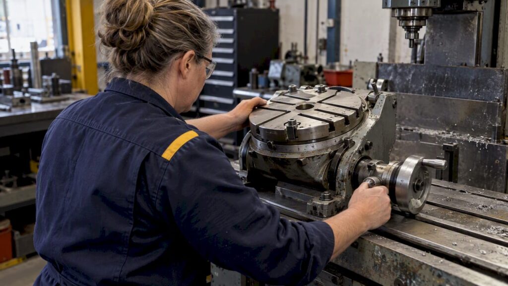
A tilting rotary table is a machining accessory that indexes and tilts a workpiece so you can cut angled faces, cones and compound surfaces on a standard mill. It suits precision machinists and production shops running 3 and 4-axis jobs that need rotary motion without a full 5-axis machine. Before buying, check table diameter, rated load and accuracy, since these three specifications decide whether a table fits your machine and your work.
TL;DR:
- The rated load capacity must account for the entire workpiece, fixture, and clamps, not just the raw part weight.
- Verify T-slot width and spacing match your hardware to prevent recurring workholding issues.
- Ensure backlash and repeatability specifications are suitable for your precision needs, and check for an adjustment mechanism.
- Match the tilt range and mounting footprint to your machine’s spindle clearance and throat size, especially for large, heavy tables.
- Incorporate proper guarding and operator controls to prevent injury from nip points and entanglement risks during tilting and rotation.
Table of Contents
- Core specs and features to expect on tilting rotary tables
- Common sizes, models and typical workshop uses
- How to choose a tilting rotary table: practical selection criteria
- Installation, mounting and workholding tips
- Maintenance, backlash adjustment and calibration
- Safety, guarding and workplace compliance
- Using a tilting rotary table in 3 and 5-axis workflows
- How Anderson Group Australia helps buyers
- Contact Anderson for quotes, verified specifications and machine matchings
- Sources
- FAQ
Core specs and features to expect on tilting rotary tables
Reading a tilting rotary table spec sheet properly means knowing which numbers actually drive performance on your machine. Table diameter sets the practical fixturing area and often correlates with rated load. Tilt range (commonly 0 to 90 degrees, sometimes with a few degrees past vertical) determines what angled geometry you can reach in one setup. Centre bore size and Morse taper rating tell you what arbors or chucks will seat directly, while T-slot width and spacing govern which clamps and fixtures you can run.
- Table diameter: drives usable work area and typically scales with rated load capacity.
- Tilt range: usually 0 to 90 degrees; check for any extension past vertical if you need undercuts.
- Centre bore and Morse taper: used for centring and light arbor work, not as the primary load path for heavy parts.
- T-slot layout: width and pitch must match your clamp and fixture hardware.
- Worm-gear ratio: finer ratios allow tighter indexing resolution for divided work.
- Indexing resolution and clamping or locking mechanism: affect repeatability and how securely the table holds position mid-cut.
Build quality, particularly the worm-gear material and the housing casting, affects how much backlash creeps in over years of use and how straightforward adjustment will be later.
Common sizes, models and typical workshop uses
Tilting rotary tables are generally grouped by diameter, and the size you need follows from the machine and the parts you run.
- Small tables: suit bench mills and light tooling or jig work where footprint and swing clearance are tight.
- Medium tables: the common choice for general tool room and job-shop work on column mills, balancing capacity against spindle clearance.
- Large tables: used on machining centres and heavier column mills for bigger fixtures, multi-part batches or production indexing.
Larger tables carry more mass and inertia, which changes fixturing strategy: you will fight more vibration at high feed rates and need stouter clamping. Matching table size to machine throat and spindle clearance matters as much as matching it to the part.
How to choose a tilting rotary table: practical selection criteria
Selecting a table is a matter of working through load, accuracy and mechanical fit in order, rather than picking on diameter alone.
- Match rated load to workpiece mass, including the fixture and any clamps, not just the bare part.
- Check centre bore and T-slot compatibility against your existing arbors, chucks and clamp hardware; mismatched T-slot widths are a common cause of poor workholding, so verify slot width before buying fixturing.
- Assess accuracy: ask about backlash figures, repeatability and whether the worm gear has an adjustment mechanism, since a table with no adjustment path will only get worse with use.
- Inspect the tilt mechanism and lock: dual-screw locks hold tilt angle more securely under cutting load than a single clamp.
- Confirm indexing resolution suits your finest required division, checking the worm-gear ratio against the job rather than assuming a standard ratio will do.
- Check mounting footprint and swing clearance on your machine before ordering.
- Consider a trunnion-style table when the job calls for simultaneous multi-axis motion rather than sequential tilt-then-index work, since a true trunnion integrates better into 4 and 5-axis CAM workflows.
Installation, mounting and workholding tips
Getting the table bolted down correctly affects every job you run on it afterwards.
- Clean and dowel the datum face before bolting, and torque fasteners in a consistent sequence to avoid distorting the base casting.
- Verify T-slot width against your clamp set rather than assuming a standard size; small and medium tables commonly run 12 mm or 14 mm slots, and a mismatch here causes recurring workholding problems.
- Use the centre bore and Morse taper for centring and light arbor work, not as the main support for heavy parts; let T-slot clamping and the table face carry the load.
- Sweep clearance through the full tilt range before cutting, checking spindle, chuck and cutter against the table body and any fixturing at every angle you plan to use.
Maintenance, backlash adjustment and calibration
Routine checks catch wear before it shows up as a scrapped part.
- Lubricate the worm gear on the schedule the manufacturer sets, and inspect for metal particles in the grease, a sign of accelerating wear.
- Watch for rising backlash, unusual noise or binding when tilting or indexing; any of these signals it is time to check adjustment.
- Measure backlash with a dial test indicator against a fixed reference, then run a repeatability check by indexing to the same position from both directions.
- Calibrate with DTI runs for manual tables, or a ballbar or laser test where the table is integrated into a CNC axis, and a 90-day ballbar testing plan is a practical way for buyers to verify a newly installed machine. Keep records for any table running serial production work.
Pro Tip: Make small backlash adjustments on a regular schedule rather than waiting for a large repair; practitioners who adjust the worm gear frequently retain indexing performance far better than those who leave it until the table binds.
Safety, guarding and workplace compliance
Rotating and tilting mechanisms carry nip-point and entanglement risk, so guarding and control design are not optional extras.
- Guard rotating shafts and tilt mechanisms so operators cannot reach a nip point during normal use, following the guarding principles set out for plant and rotating machinery.
- Design operator controls to be identified, conveniently located, lockable and fail-safe, which is a core expectation for controlling plant risk.
- Assess entanglement and nip-point risk specific to the tilt axis, not just the rotary axis, since the tilting motion introduces a second pinch point that a purely rotary table does not have.
- Train operators on lockable off positions and on isolating the table before adjusting fixtures.
Guarding is the primary control for preventing injury from rotating machinery in a workshop, according to Safe Work Australia’s plant risk guidance. Woodworking-specific guidance also flags nip-point and entanglement risk as a recurring cause of injury around rotating machinery, reinforcing why guarding and training both matter here.
Using a tilting rotary table in 3 and 5-axis workflows
CAM setup matters as much as the physical table when a tilting rotary table feeds into multi-axis work.
- Set tool axis limits in your CAM software to catch collisions before they happen, a practice recommended for simultaneous multi-axis machining.
- Favour rotary pocket, rotary parallel or rotary contour toolpaths for rotary operations, and treat high-tilt deburring paths with caution since extreme tilt angles raise collision risk.
- Calibrate the table’s rotation axis to the spindle mechanically, because joint clearance and worm backlash are recognised contributors to kinematic error that software compensation alone cannot fully correct.
- Secure the workpiece against vibration at the tilt angle you intend to cut at, not just at zero tilt, to protect surface finish.
How Anderson Group Australia helps buyers
A supplier of CNC machinery, servicing and parts can help confirm whether a tilting rotary table and its mounting hardware suit your mill or machining centre. For woodworking, cabinet and joinery work, our Wood Machinery range and the Genesis PLUS nesting machine cover panel processing and nesting; confirm any rotary accessory against the exact machine, controller, workholding and safety configuration rather than assuming compatibility. For metal and aluminium milling, our Metal Machinery range, including Focaseiki machining centres, suits rotary and trunnion-style setups in multi-axis work. Send us your drawings or machine details and we will check fitment before you order.
Contact Anderson for quotes, verified specifications and machine matchings

Choosing the right tilting rotary table means matching it to a machine you already trust, and Fit checks can be done before you commit to a purchase.
- Woodworking, cabinet and joinery shops: start with Wood Machinery or the Genesis PLUS nesting machine page.
- Metal and aluminium milling: review Metal Machinery for Focaseiki machining centres suited to rotary and trunnion fixturing.
- Not sure which machine fits your table and workpiece: visit our machines landing page or send us your part drawings for a specification check and quote.
Sources
- PhD thesis on kinematic error models (Jiang 2015)
- Managing the risks of plant in the workplace (Safe Work Australia)
- Haas 5-axis induction (UNSW)
- Guide to safe use of woodworking machinery (WorkSafe WA)
FAQ
What are the common problems with rotary tables?
The most common issues are rising backlash in the worm gear, binding or noise during tilt or index motion, and workholding failures caused by mismatched T-slot widths. Regular lubrication checks and small, frequent backlash adjustments prevent most of these problems from becoming serious.
What is a tilting table?
A tilting table is a workholding accessory that pivots a workpiece through an angular range, commonly up to 90 degrees, so you can machine angled or compound faces without resetting the fixture. A tilting rotary table combines this tilt function with a rotary indexing table in one unit.
What are the two main types of rotary tables?
Rotary tables are broadly split into horizontal rotary tables, which only index around a single vertical axis, and tilting rotary tables, which add a second axis of motion by pivoting the table through an angular range. Trunnion-style tables are a further variant built for simultaneous multi-axis motion on 4 and 5-axis machines.
What is the difference between a rotary table and a dividing head?
A rotary table mounts flat on the machine bed and indexes a workpiece around a vertical axis, suiting larger fixtures and heavier parts. A dividing head mounts on its own stand at spindle height and is generally used for smaller precision division work, such as gear cutting or indexing on cylindrical parts held between centres.