
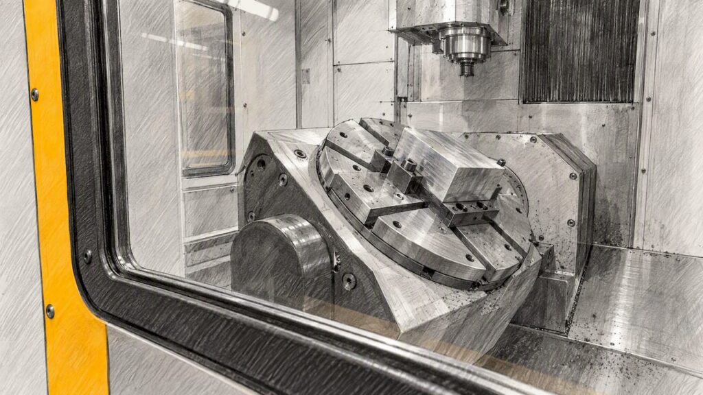
A dynamic work offset (DWO) is a CNC control function that moves the work-coordinate origin to follow a part after the rotary axes have indexed. It is built for 3+2 machining, where the rotary axes position the part and lock, then the three linear axes cut. It is not a substitute for tool centre point control (TCPC) on simultaneous 5-axis work. On some controls it is called G254, and other controls use different names or codes, so always confirm against your own machine’s manual.
This guide is for production engineers and shop owners in Australia who are specifying or running machining centres with a rotary table or trunnion. It separates documented facts, which are cited, from general guidance, which is labelled as such.
TL;DR
- A DWO shifts the work origin to follow an indexed rotary position. The X, Y and Z directions stay aligned with the machine axes (UNSW Making).
- It suits 3+1 and 3+2 positioning. It does not replace TCPC for continuous, simultaneous 5-axis cutting.
- The payoff is placement freedom: you can load the fixture where it suits and let the control account for the difference, instead of rebuilding the program.
- Before running it, match the machine mode to the G-code, model tools, holders and workholding accurately, and physically check tight clearances.
- Whether a given machine offers DWO depends on the exact control and configuration. Never assume it from the axis count or the family name.
Table of Contents
- What a dynamic work offset actually does
- A simple worked example
- DWO versus TCPC and simultaneous 5-axis
- Setting up a DWO: a sensible sequence
- Safety checks that belong with DWO work
- Accuracy: what DWO cannot fix
- What to confirm before buying a machine for DWO work
- Where this applies in a wood and panel shop
- Machining centres for indexed metal work
- Talk to us about your application
- FAQ
- Sources
What a dynamic work offset actually does
A normal work offset (G54 and its siblings) records where the part zero sits relative to the machine zero. That works well while the rotary axes stay at zero. Once a rotary axis indexes, the part swings around the centre of that axis, and the part zero moves in machine space. Without compensation, the program cuts where the origin used to be.
A DWO is the control’s way of handling that. UNSW Making’s teaching notes describe it as a translation of the work origin after the rotary B and C axes have indexed, while the XYZ directions remain the same as the machine axes (UNSW Making). In plain terms, the origin follows the part. The axis directions do not rotate with it.
That last point is the one people trip over. The control knows where the origin went. It does not re-tilt your coordinate system. Tilted-plane commands and TCPC do something different, covered below.
Why it matters on the shop floor
In many CAM workflows, the program assumes the fixture sits at a specific spot on the table. Any difference between that assumed spot and the real one has to be dealt with somewhere. Common options are:
- Re-post the program with new coordinates.
- Fixture the part at exactly the programmed location.
- Measure the real position and let the control compensate.
A DWO is the third option. The CAM programmer works from the part and the fixture model, and the operator measures where things actually landed and enters the relevant geometric offsets. The idea is that you can place the part and fixture anywhere on the table and still run the same program. That is a general description of the function from vendor and training material, not a promise about any specific machine’s performance.
A simple worked example
This example uses invented round numbers purely to show the logic. It is not a measurement from any machine.
Imagine a part zero sitting 100 mm above the centre of a rotary table’s axis. The CAM program was written with the table at 0 degrees. When the table indexes to 90 degrees, the part’s top surface no longer faces the spindle in the same place: the point that was 100 mm above the pivot is now 100 mm to the side of it.
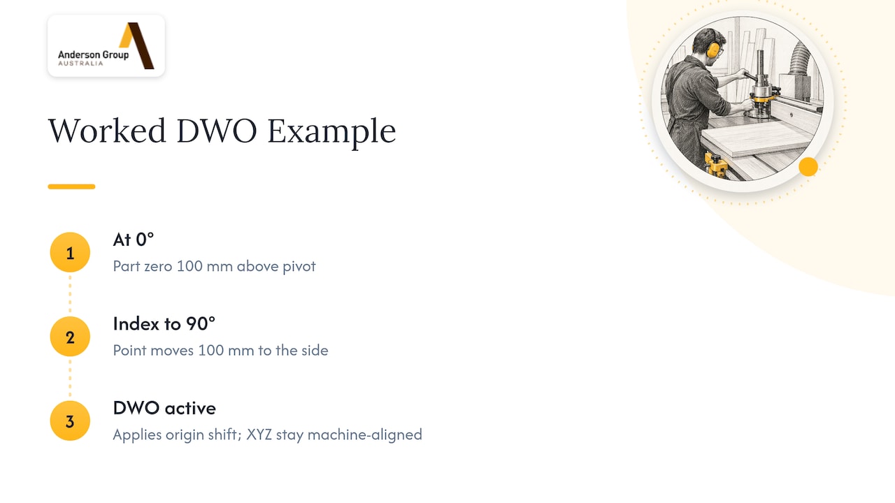
Without a dynamic offset, the control would still think the origin is where it was at 0 degrees. With a DWO active, the control uses the pivot-point geometry you have entered, works out where the origin now sits at the indexed angle, and applies that shift. The tool then cuts the feature at the right place on the part.
The quality of that result depends on the quality of the numbers you enter. The pivot distances, table centre position and any offsets between axes all come from calibration and probing, not from the program. If those are wrong by a small amount, every indexed face inherits the error. For a deeper look at how datums and clamping decisions drive accuracy, see our guide on CNC workholding methods with datum logic.
DWO versus TCPC and simultaneous 5-axis
The two functions solve different problems, and mixing them up is where crashes start.
| Dynamic work offset | Tool centre point control (TCPC) | |
|---|---|---|
| Typical use | 3+1 and 3+2 positioning | Simultaneous 4- and 5-axis cutting |
| Rotary axes while cutting | Indexed, then locked | Moving continuously |
| What it compensates | Origin position and pivot distances | Full tool tip position as rotary axes move |
| Axis directions | Stay aligned with machine axes | Control computes the tool orientation throughout |
| Main risk | Wrong pivot or offset data, or using it with rotary motion | Unsimulated rapid moves, kinematic mismatch |
GibbsCAM’s documentation draws the same line. Its dynamic work fixture offset moves the working origin with the rotating part, but it does not rotate the axis directions, and it solves origin and pivot-distance changes rather than the complete tool-tip kinematics (GibbsCAM Compost Wiki). It also notes that most controls do not recommend rotary motion while cutting in this mode, because the tool tip is not guaranteed to follow the programmed path the way it is under full TCP.
Simultaneous 5-axis machining, by contrast, involves dynamically orienting the tool throughout the cut, as Siemens describes in its programming guide for dynamic 5-axis machining. That is the territory of TCPC, and it needs the control to carry a full kinematic model of the machine.
Not every control does this for you
Some controls leave the kinematics to the CAM system. MASSO’s documentation, for example, states that its controller does not do kinematic calculations and does not support TCP, RTCP or TCPC, so the user’s CAM software has to handle all of it (MASSO 5-axis documentation). The lesson is general: before you plan a workflow around DWO or TCPC, find out which of the two the control actually provides and which side, control or CAM, owns the maths.
Setting up a DWO: a sensible sequence
The steps below are general guidance for how a careful shop approaches this. Your control’s manual and the machine builder’s instructions come first, and the exact names of the parameters and G-codes differ between controls.
- Confirm the function exists on your control and configuration. Check the exact model, control option list and rotary hardware. Do not infer it from the number of axes.
- Calibrate the rotary axes. Establish the table or trunnion centre and the pivot distances the control needs. Use a probe or a method the machine builder recommends.
- Define the geometric offsets. Enter the values the control requires for the rotary axes and the fixture. These are the numbers the DWO uses to calculate the origin shift.
- Set the work offset on the real part. Touch off where the program expects its origin, using the same datum scheme as the CAM setup.
- Match the program to the machine mode. The G-code must be posted for the mode you are running. A mismatch between post and mode is a common cause of wrong moves.
- Simulate with accurate models. Include tools, holders, stock and workholding, then verify the tightest clearances physically with a dry run.
- Re-verify after any change. New fixture, new tool, new post, new machine configuration: check again.
Tool length data feeds directly into this. A small error in the tool length shifts every indexed face, so it is worth reading about tool length setter repeatability alongside your DWO setup. If you run repeat work, a zero-point fixturing system can reduce how much you rely on compensation by returning fixtures to the same place each time.
Safety checks that belong with DWO work
Indexed machining brings the spindle, tool and holder close to fixtures and rotary hardware from angles the programmer may not have pictured. These checks come from the sources cited.
- Use DWO for 3+2, not simultaneous machining. UNSW’s guidance is to match the machine mode to the G-code when checking clearance, model tools, holders, stock and workholding accurately, and physically verify tight clearances. It also suggests using the control’s safe-run feature if you are uncertain (UNSW Making).
- Do not trust simulation alone for rapids. The same guidance warns that TCPC rapid moves can cause collisions that the simulation does not show.
- Do not bypass safety devices. SafeWork SA’s 2023 alert states that CNC safety devices must not be bypassed, and that businesses should provide instruction and training and test safety devices before operation (SafeWork SA).
- Treat a changed setup as a new risk. Safe Work Australia’s guidance on managing work health and safety risks says controls should be reviewed when they are ineffective, when equipment or work methods change, or when new hazards are identified (Safe Work Australia). A new fixture position, program or tool set is exactly that kind of change.
Putting a named person in charge of first-off proving, and writing the proving steps down for each new fixture, is general good practice. It is not a legal prescription, and your own WHS obligations in your state or territory apply.
Accuracy: what DWO cannot fix
A DWO moves the origin. It does not make a loose fixture rigid, correct a warped part, or turn a poorly calibrated rotary axis into a good one. Your tolerance budget still depends on workholding, thermal behaviour, tooling and the machine’s own geometry. If you are setting tolerances for a job, our guide to CNC tolerances tied to ISO 2768 helps you choose realistic limits. For work in aerospace-type industries, the aerospace CNC machining guide covers what engineers should specify.
What to confirm before buying a machine for DWO work
If indexed 3+2 work is part of your plan, put these questions to any supplier, including us, before you commit:
- Which exact model and configuration? A family name or axis count does not tell you whether a rotary table, trunnion, pallet changer or probe is fitted.
- Which control, and which options? Ask whether dynamic work offset or an equivalent is available on that control, what it is called, and whether it is included or an option.
- Does it also offer TCPC? If you may later want simultaneous machining, check this now.
- What does your CAM and post workflow support? The post must match the machine mode.
- How is calibration done? Ask what probing and rotary-axis calibration the machine supports.
- Pallet changing and fixturing. If you plan to run fixtures on pallets, confirm the exact model supports the pallet system and how fixtures are located.
This is also where cost thinking helps. Setup time, proving time and fixture design all sit inside the real cost of ownership, which we cover in our CNC lifecycle cost modelling guide. Better planning at the setup stage also supports uptime, as discussed in improving CNC uptime.
Where this applies in a wood and panel shop
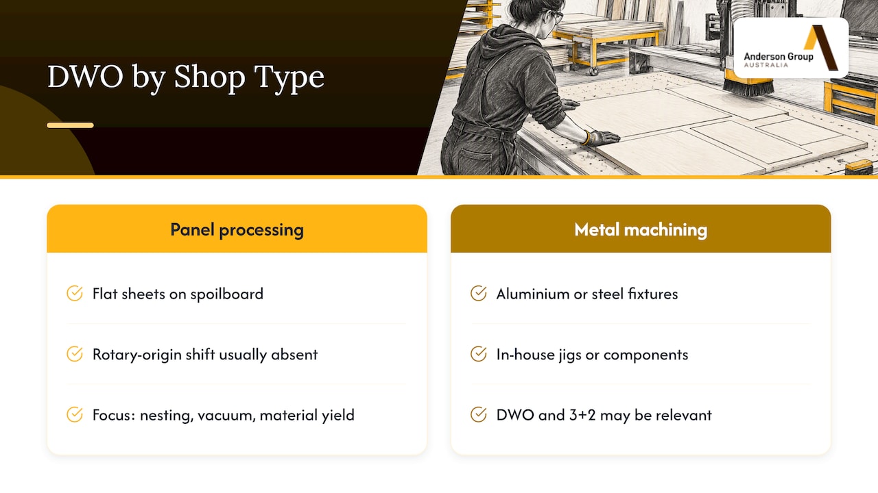
Most of our customers are kitchen, cabinet, joinery and furniture manufacturers, so it is worth being direct: DWO is mainly a metal-machining and multi-axis topic. A flatbed nesting router cuts sheet material held flat on a spoilboard. The panel sits in one plane, and the part zero is set on the table, so the rotary-axis origin shift that DWO addresses does not normally arise in that kind of work. That is general guidance rather than a specification of any one machine.
For panel processing, the decisions that move your output are different: nesting layout, vacuum holding, tool management, offcut handling and material yield. If that is your world, start with how to increase CNC nesting productivity and how to reduce CNC waste. Our wood machinery range is where to look for nesting and panel-processing machines.
If your shop also machines aluminium or steel fixtures, jigs or components in house, then DWO and 3+2 workflows may well be relevant to you, and the metal side of our range is the place to start.
Machining centres for indexed metal work
For metal and aluminium milling, we supply Focaseiki machining centres. Our metal machinery range and the machines overview list the categories, including vertical machining centres, machines with automatic pallet changing, double column machines and 5-axis vertical machining centres. Individual pages, such as the VMC-600/860/1160 vertical machining centre and the VMC-1100/1250/1400, carry the documented specifications for those models.
We do not state here that any particular model includes DWO, TCPC, a rotary table, probing or pallet changing. Those depend on the exact model, control and configuration, and we would rather confirm them against the product page and the quote than have you assume.
We sell machinery, servicing and parts for your own production. We do not offer subcontract cutting or machining.
Talk to us about your application
If you are weighing up a machining centre for indexed 3+2 work, or a nesting machine for panel production, tell us what you make, the materials, the part sizes and the volumes. We will point you to the models that fit and confirm the options against the documentation.
Start with our machines page for metal machining centres, or the wood machinery page for kitchen, cabinet and joinery production, then contact us to discuss your application or request a quote.
FAQ
What is a dynamic work offset in simple terms?
It is a control function that moves the work origin to follow a part after the rotary axes index. The XYZ directions stay aligned with the machine axes. It is mainly used for 3+2 machining, where the rotary axes lock before the linear axes cut.
Is a dynamic fixture offset the same as a dynamic work offset?
The names are used for the same idea in many places, and the naming varies between controls and CAM systems. GibbsCAM, for example, calls its version a dynamic work fixture offset (GibbsCAM Compost Wiki). Check your control’s manual for the exact function and code.
Can I use DWO for simultaneous 5-axis machining?
No. It is designed for 3+1 and 3+2 positioning, and the documentation we reviewed advises against rotary motion while cutting in this mode. Simultaneous work needs tool centre point control, and the control or the CAM system must handle the kinematics.
Do nesting routers need a dynamic work offset?
Normally not. Flat panel nesting sets the part zero on the table in one plane, so there is no indexed rotary origin to follow. DWO is a multi-axis metal and mixed-material machining topic, and your machine choice should follow your application.
How do I know if a machine supports DWO?
Ask for the exact model, control and option list in writing. Do not infer it from the axis count or the family name. We can confirm what is documented for our models when you contact us.
Sources
- Haas 5-axis: 3+2 induction, UNSW Making
- Dynamic WFO, GibbsCAM Compost Wiki
- Programming dynamic 5-axis machining, Siemens SINUMERIK live
- 5 Axis Machining, MASSO documentation
- Dangers of bypassing safety devices, SafeWork SA
- How to manage work health and safety risks, Safe Work Australia