
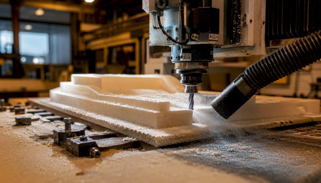
Choose a foam-cutting process from the material grade, part geometry and required finish, rather than the word “foam” alone. Before comparing equipment, prepare the stock dimensions, drawings, smallest features and examples of an acceptable edge or surface. Ask the supplier to assess the proposed material and tooling in a representative trial; do not assume every foam grade suits the same process.
Here is the quick decision rule: dense, closed-cell foams (polyurethane tooling boards, XPS, HDU) suit CNC routing because they hold geometry well and resist melting. EPS and lightweight open-cell foams work better with hot-wire or knife cutting for large, low-detail forms. Waterjet handles thick structural cores without heat. Wire profiling is the go-to for tapered wing sections and constant cross-section extrusions.
Recommended method by common use case:
-
Prototype parts and concept models: CNC router with an O-flute end mill; dense PU tooling board or HDU
-
Tooling patterns and mould plugs: 3-axis or 5-axis router; HDU or Renshape-class PU board
-
Custom packaging inserts: knife cutting or CNC routing; PE or EVA foam
-
Large set pieces and architectural props: CNC router with long-reach tooling or hot-wire for rough shaping, then router finishing pass
-
Structural composite cores: waterjet or dry router; Divinycell or Rohacell-class PVC/PMI foam
Safety and finish trade-offs to know upfront: EPS and XPS melt rather than cut cleanly if spindle speed is too high or feed rate too slow. Foam dust is highly static and accumulates fast in machines, so dust extraction and anti-static grounding are not optional. Polyurethane dust from some formulations carries isocyanate residues and requires respiratory protection.
Key takeaways
Foam CNC machining is reliable and cost-effective when you match the cutting method to the foam type, specify tolerances that the material can actually hold, and manage dust and heat from the first cut.
| Point | Details |
|---|---|
| Method selection drives outcomes | Match your cutting method to foam density and shape: routing for dense PU/HDU, hot-wire for large EPS forms, waterjet for structural cores. |
| Spec your job completely | Send STEP files, density, tolerances, finish requirements, and quantity to get an accurate quote without back-and-forth. |
| Dust and heat are the main risks | Use O-flute tooling, fast feed rates, vacuum workholding, and anti-static extraction on every foam job. |
| Buy vs hire depends on volume | In-house equipment makes sense above roughly 20–30 machine hours of foam work per month; below that, contracting out is more flexible. |
| Anderson for in-house capability | Anderson’s 5-axis and enclosed CNC machines are suited to foam and advanced materials work, with local service support across Australia. |
Table of Contents
-
Why CNC foam cutting delivers results that manual methods cannot
-
What foam CNC cutting methods are available, and when does each one fit?
-
Which foam materials can you machine, and what are the trade-offs?
-
From CAD file to finished part: the workflow an Australian shop follows
-
What does foam CNC machining cost in Australia, and how long does it take?
-
Where foam CNC machining is used across Australian industries
-
Anderson Group Australia: CNC equipment for foam and advanced materials
Why CNC foam cutting delivers results that manual methods cannot
CNC foam cutting gives you repeatability that hand-cutting simply cannot match, especially once you move past the first prototype. Every part comes off the machine to the same geometry, which matters the moment you are producing more than a handful of pieces or feeding foam components into a downstream assembly process.
The practical advantages that drive the decision to use CNC:
-
No hard tooling cost: unlike injection moulding or cast urethane, you pay for machine time, not a mould. For short runs of 1–50 parts, this is almost always cheaper.
-
Complex 3D contours on demand: a 3-axis router handles compound curves that would take hours by hand; a 5-axis machine handles undercuts and organic geometry in a single setup.
-
Quick design iteration: change the CAD file, re-post the toolpath, and cut a revised part the same day. Physical mould changes take days or weeks.
-
Consistent surface finish: a well-dialled toolpath on dense foam produces a finish that needs only light sanding or a single coat of primer before painting.
CNC is not always the right answer. Very low-budget jobs with no dimensional tolerance requirement, or very soft open-cell foams that compress under any clamping force, are often better handled by die-cutting or knife plotting. The economics also shift: if you need one large rough shape in EPS, a hot-wire cutter costs a fraction of a CNC router hour.
Pro Tip: Before committing to in-house equipment, run three to five contract jobs through a foam machining service. You will learn your actual volume, the tolerances you genuinely need, and whether the machine hour rate justifies capital expenditure. Australian shops generally break even on in-house foam CNC equipment at a moderate monthly usage level.
What foam CNC cutting methods are available, and when does each one fit?
Four main methods cover the vast majority of foam work. Each has a natural home based on material, shape, and finish requirements.
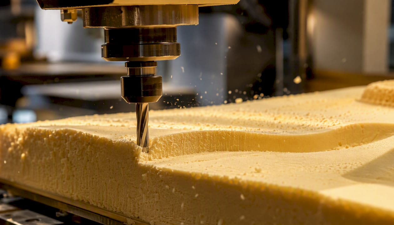
CNC routing is the most versatile option. A spindle-driven end mill removes material in three to five axes, handling everything from flat panel profiling to full 3D sculpture. Tight tolerances within a small fraction of a millimeter are achievable on dense foams. The main risk is heat: too slow a feed rate and the cutter dwells long enough to melt EPS or XPS. CNC routers handle large single-piece carvings and accept long-reach tooling and rotary axes for organic geometry, which makes them the most flexible choice for Australian shops running varied work.
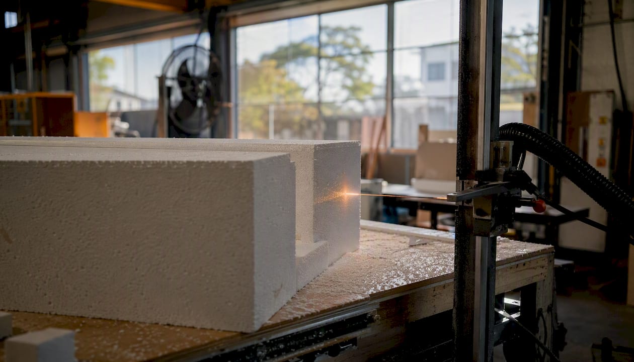
Hot-wire cutting uses a resistively heated wire to slice through EPS and XPS without generating dust. It is fast for large, simple forms and produces a smooth, sealed surface. The limitation is geometry: the wire must travel in a straight line or a ruled surface, so undercuts and true 3D contours are not possible. Tolerances are typically ±1–2 mm.
Knife cutting (oscillating or drag knife) suits soft, compressible foams such as PE, EVA, and open-cell acoustic foams where a spinning cutter would tear rather than slice. It produces clean edges on thin sheet material and is common in custom packaging and gasket work.
Waterjet cutting uses a high-pressure water stream, sometimes with abrasive, to cut through thick structural foam cores (PVC, PMI, Rohacell) without any heat-affected zone. It is slower than routing for simple profiles but avoids the melting risk entirely on heat-sensitive materials.
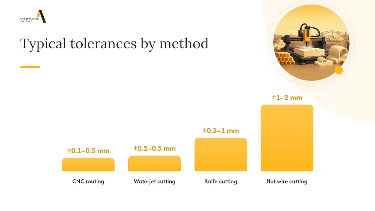
| Method | Typical tolerance | Best foam families | Dust/heat risk | 3D contours |
|---|---|---|---|---|
| CNC routing | ±0.1–0.5 mm | PU board, HDU, XPS, EPS | Dust high; heat moderate | Yes (3–5 axis) |
| Hot-wire | ±1–2 mm | EPS, XPS | None | Ruled surfaces only |
| Knife cutting | ±0.5–1 mm | PE, EVA, open-cell | None | 2D profiles only |
| Waterjet | ±0.2–0.5 mm | PVC core, PMI, thick EPS | None | 2D profiles, some 3D |
Post-processing notes: routed PU tooling board and HDU sand cleanly and accept primer directly. EPS routed surfaces show a textured cell pattern that needs a sealer coat (latex paint or a product like Foam Coat) before painting. Hot-wire surfaces on EPS are already sealed and paint-ready. Waterjet-cut edges on structural cores are dry and bond-ready for composite layup.
As NIST special publication 847 documents, advanced and brittle materials often require modified machining methods and specialised tooling, and foam is no exception: matching the process to the material’s cellular structure is what separates clean parts from melted or torn ones.
Which foam materials can you machine, and what are the trade-offs?
The foam family determines almost everything about how you set up the job.
-
EPS (expanded polystyrene): lightweight, cheap, widely available. Melts easily if feed rate is too low or RPM too high. Best cut with hot-wire for large forms; router works well with O-flute tooling and fast feeds. Dust is voluminous and highly static.
-
XPS (extruded polystyrene): denser and more dimensionally stable than EPS. Routes cleanly at moderate speeds. Same melting risk as EPS; same dust management requirements.
-
Polyurethane (PU) tooling board: the preferred material for precision foam CNC machining. Available in densities from around 100 kg/m³ to 800 kg/m³. Higher-density grades hold tolerances of ±0.1 mm and machine like a soft hardwood. Dust from some PU formulations contains residual isocyanates; respiratory protection and extraction are mandatory.
-
HDU (high-density urethane): similar to PU tooling board, used extensively for sign-making, architectural mouldings, and marine patterns. Machines cleanly with standard router tooling.
-
Polyethylene (PE) and EVA: flexible, closed-cell foams used in packaging and orthotics. Tend to compress under clamping; knife cutting or vacuum fixturing with a spoilboard is standard. Router cutting works but requires sharp tooling to avoid tearing.
-
PVC structural core (Divinycell-class): used in composite sandwich panels for marine and aerospace. Structural core foams machine predictably when spindle speed, feed, and entry strategy match the foam’s cellular structure; vacuum workholding and compressed air chip evacuation are standard shop practice.
-
PMI (polymethacrylimide, e.g. Rohacell): high-performance aerospace core. Brittle at low densities; requires light cuts and ramping entries. No coolant or lubricant; dry machining only to avoid contaminating the cell structure before resin infusion.
-
Acoustic foams (melamine, open-cell PU): very soft and compressible. Knife cutting preferred; routing tears the surface unless the foam is frozen or backed with a rigid spoilboard.
Single-flute O-flute end mills and high feed rates are the standard starting point for most foam types to avoid melting and fuzzing. For styrofoam-class materials, running spindle speed around 10,000 rpm with fast feed rates reduces heat build-up; finishing with latex paint or Foam Coat hides the cell texture.
Material callout: PU dust from tooling boards is the most significant health hazard in foam machining. Australian workplaces are governed by Safe Work Australia’s model WHS Regulations; isocyanate-containing dust requires local exhaust ventilation and, where extraction cannot reduce exposure below the workplace exposure standard, supplied-air or P2 respirators.
From CAD file to finished part: the workflow an Australian shop follows
Getting a foam part right the first time comes down to how well the job is prepared before the machine starts. Here is the sequence:
1. CAD geometry check Confirm the model is watertight (no open surfaces), all radii are achievable with available tooling, and wall thicknesses are at least 3× the cutter diameter for dense foams (thinner walls deflect under cutting forces).
2. CAM strategy Select toolpaths that ramp or helical-plunge into the material rather than plunging straight down. Straight plunges compress foam and can tear cell walls. For 3D contours, a scallop or parallel finishing pass at high feed rate gives the best surface.
3. Tooling selection O-flute (single-flute) end mills are the default for most foam work. They clear chips aggressively and reduce heat. Ball-nose tools suit 3D finishing; straight-flute compression bits suit through-cuts in sheet foam where top and bottom edge quality both matter.
4. Fixturing Vacuum tables are the most common solution for sheet foam. For block work, double-sided tape on a spoilboard works well for small parts. Soft-jaw fixtures or foam-lined clamps suit irregular shapes. Vacuum workholding and compressed air chip evacuation protect cell structure and prevent tool binding on structural core foams.
5. Dust extraction Foam dust is highly static and accumulates rapidly. Grounding the vacuum hose or using anti-static hoses reduces clogging and static build-up inside the machine cabinet. A dedicated cyclone separator upstream of the main dust collector extends filter life significantly.
6. Finishing Dense PU and HDU: sand with 120–180 grit, prime, paint. EPS/XPS: seal with latex or Foam Coat before any solvent-based paint (solvents dissolve EPS). Structural cores for composite use: dry, clean, bond immediately.
Pro Tip: Before running a full batch, cut a single test piece at final material and finish. It costs one part’s worth of material and machine time, but it will surface fixturing problems, melting issues, and finish surprises before they affect 50 parts. This is especially worth doing when switching foam density or supplier.
How to spec your foam CNC job so you get an accurate quote
Australian foam machining shops quote faster and more accurately when you send a complete specification upfront. Missing information means the shop has to assume worst-case parameters, and you pay for that uncertainty.
Job spec checklist:
-
3D file: STEP or IGES for machined parts; STL is acceptable for reference but not preferred for toolpath generation. Include a PDF drawing with critical dimensions called out.
-
Units and scale: confirm mm or inches; confirm the file is 1:1 scale.
-
Material: foam type, density (kg/m³), and preferred supplier or grade if you have one.
-
Tolerances: state the critical dimensions and their tolerance band. Foam is not metal; ±0.5 mm is achievable on dense PU, ±1–2 mm is realistic on EPS.
-
Surface finish: specify which faces need a machined finish and which are cosmetic. Note if sealing, painting, or bonding is required.
-
Quantity: prototype quantity (1–5) versus short run (6–50) versus production run (50+). Pricing changes significantly across these bands.
-
Fixturing constraints: note any faces that cannot be clamped or taped (bonding surfaces, cosmetic faces).
-
Lead time: state your required delivery date and whether you need a test cut first.
-
Post-processing: painting, coating, laminating, or bonding requirements.
Common questions shops will ask:
-
Can the part be flipped for a two-sided operation, or does it need a custom fixture?
-
Is the tolerance on the overall envelope, or only on specific features?
-
Is the foam supplied by you or sourced by the shop?
Pro Tip: Configure a foam tool library in your CAM software once you have validated a stable RPM, feed, and tool combination. It eliminates repeat setup errors and makes re-quoting faster when you return with a revised part.
Tolerancing foam is different from tolerancing aluminium. Dense PU tooling board holds ±0.1–0.2 mm on a well-maintained machine. EPS and open-cell foams are compressible and springy; expect ±0.5–1.5 mm and design features accordingly. If your application genuinely needs sub-0.5 mm tolerance in foam, specify a high-density PU board and confirm the shop’s machine calibration before committing.
What does foam CNC machining cost in Australia, and how long does it take?
Price is driven by a handful of variables, and understanding them helps you evaluate quotes rather than just accept the first number.
Cost drivers:
-
Material: EPS is cheap; high-density PU tooling board can cost $200–$600+ per block depending on grade and size. Material cost often exceeds machine time on small prototype runs.
-
Part complexity: a flat panel profile costs a fraction of a full 3D sculpture. Each additional axis of movement adds setup time and programming cost.
-
Tolerances and finish: tighter tolerances mean slower feeds, more passes, and more inspection time.
-
Quantity: setup and programming are fixed costs spread across the run. A single prototype carries the full setup cost; 20 identical parts amortise it.
-
Machine hour rate: Australian CNC shops typically charge by the hour for machine time, with rates varying by machine type, axis count, and location.
-
Fixturing: custom fixtures for complex parts add cost on the first run but are amortised over repeat orders.
| Job type | Indicative lead time | Notes |
|---|---|---|
| Single prototype (simple geometry) | 2–5 business days | Assumes material in stock |
| Single prototype (complex 3D) | 5–10 business days | Programming and test cut time |
| Short run (10–50 parts) | 1–3 weeks | Depends on queue and fixturing |
| Large architectural/set piece | 2–4 weeks | Material sourcing and multi-setup work |
When does buying equipment make sense? If your shop is running more than 20–30 hours of foam work per month consistently, the economics of in-house equipment start to stack up. Below that threshold, contracting out gives you flexibility without capital commitment. The calculation also depends on whether foam is your primary material or one of many: a machine bought for foam that sits idle between foam jobs is expensive overhead.
What to look for when buying a CNC machine for foam work
Foam is forgiving on cutting forces but demanding on dust management, spindle speed range, and travel envelope. The machine attributes that matter most are different from what you would prioritise for aluminium or steel.
Key specifications to evaluate:
-
Travel envelope: foam parts are often large. A machine with 2,400 × 1,200 mm or larger table capacity handles full sheets and avoids the cost of joining multiple machined pieces.
-
Spindle speed range: foam needs high RPM (18,000–24,000 rpm for most routing work) combined with fast feed rates. A spindle that tops out at 12,000 rpm will struggle with EPS and XPS.
-
Axis count: 3-axis handles the majority of foam work. A 4-axis rotary attachment opens up cylindrical and tapered forms. 5-axis machining is worth the investment when your parts have undercuts, compound angles, or organic geometry that would otherwise require multiple setups.
-
Vacuum table: non-negotiable for sheet foam work. Zone-controlled vacuum lets you hold partial sheets without losing suction.
-
Dust extraction integration: enclosed machines with integrated extraction keep foam dust contained. The MASS-B enclosed 5-axis machine is an example of a design where dust control is built into the machine architecture rather than bolted on.
-
O-flute tooling compatibility: confirm the spindle collet range accepts the shank diameters of the O-flute cutters you plan to run.
-
Automation options: if an auto pallet changer with zero-point system is being considered, confirm compatibility with the selected machine, fixture and foam-production workflow before comparing setup requirements.
-
Service and parts support in Australia: a machine is only as good as the support behind it. Confirm local technician availability and parts lead times before purchasing.
Pro Tip: For very large foam work (architectural installations, full-scale set pieces, boat hull plugs), a large-travel 5-axis machine like the MASS-5 lets you machine a full-scale form in one setup, eliminating the join lines and registration errors that come from stitching multiple smaller cuts together.
Where foam CNC machining is used across Australian industries
Foam CNC work shows up across a wider range of sectors than most people expect.
-
Aerospace and defence tooling: PU and PMI foam boards machined to precise profiles for composite layup mandrels, vacuum bag caul plates, and inspection fixtures. Tolerances are tight; material traceability matters.
-
Marine: EPS and PVC core foam machined for hull plugs, deck moulds, and sandwich panel cores. Large travel envelopes and 5-axis capability are common requirements.
-
Theatre, film, and events: EPS and HDU machined into props, set dressing, architectural facades, and signage. Speed and scale matter more than tight tolerance.
-
Custom packaging: PE and EVA foam routed or knife-cut to cradle precision instruments, medical devices, or electronics. Fit is critical; CNC ensures every insert matches the product geometry.
-
Acoustic panels: melamine and open-cell PU foam cut to profile for recording studios, auditoriums, and industrial noise control. Knife cutting is common; routing works on denser acoustic foams.
-
Architectural and signage: HDU machined into decorative mouldings, 3D lettering, and facade elements. Paints and primers bond well to HDU without sealing.
-
Prototyping and product development: foam models are faster and cheaper than 3D-printed equivalents at large scale. A product designer can have a full-scale ergonomic model in hand within a day.
A concrete example of the decision logic in practice:
A marine composites shop needs 12 identical hull plug sections in PVC structural core foam, each 800 × 400 × 150 mm, with a ±0.3 mm tolerance on the mating faces. They specify Divinycell H80, dry CNC routing with vacuum workholding, no coolant (the parts go straight into a resin infusion layup), and a machined finish on the bond faces. Programming takes half a day; each part runs in under 20 minutes. Total lead time: five business days including material delivery.
Anderson Group Australia: CNC equipment for foam and advanced materials
Anderson Group Australia supplies CNC machinery, servicing and spare parts. Confirm the exact machine configuration, installation arrangements and available support with the team.

Use Anderson’s advanced-materials machinery range as a starting point for an application discussion, not a guarantee that one model suits every foam. Confirm the proposed configuration, tooling, workholding and extraction against your material grade and part drawing. Ask separately about commissioning, training and support arrangements; enclosure design alone does not establish dust-control performance or service response time.
To discuss your foam CNC requirements or arrange a machine demonstration, contact Anderson directly.
What foam CNC shops get wrong, and how to avoid it
The most common failures in foam CNC work are not machine failures. They are process failures that show up because someone skipped a validation step or assumed foam behaves like a harder substrate.
What experienced shops do differently:
-
They always run a test cut on scrap material at the final parameters before touching the production stock. A five-minute test cut prevents a $400 block of PU tooling board from becoming waste.
-
They treat workholding as seriously as toolpath strategy. A part that shifts mid-cut on a foam job is not recoverable. Vacuum tables are preferred; double-sided tape is a backup, not a first choice.
-
They avoid straight plunge entries. Helical or ramping entries into foam protect cell structure and prevent the tearing and compression that plunges cause, particularly in open-cell and lower-density materials.
-
They manage static actively. Foam dust is one of the most static-prone materials in any shop. Anti-static extraction hoses, machine grounding, and regular filter cleaning are standard practice, not optional extras.
Common pitfalls and fixes:
-
Melting on EPS/XPS: increase feed rate before reducing RPM. Dwell time is the enemy, not speed.
-
Fuzzing on PU foam: switch to a sharper O-flute cutter; check for tool wear.
-
Poor paint adhesion after machining: EPS and XPS need a sealer coat before any solvent-based product. PU and HDU benefit from a light scuff and a spray primer.
-
Static clogging the dust collector: ground the hose, add a cyclone separator, and clean filters after every foam session.
Australian workplace safety note: Safe Work Australia’s model WHS Regulations apply to foam dust exposure in Australian workplaces. Isocyanate-containing PU dust requires local exhaust ventilation and, where necessary, respiratory protective equipment. EPS dust is a nuisance dust at high concentrations; extraction and P1/P2 masks are appropriate. Always check the Safety Data Sheet for the specific foam grade you are machining.
Sources
-
CNC Machining of Core Foam: Typical Challenges and How to Solve Them | Chem-Craft
-
Tips for CNC Foam Cutting | Woodworkers Guild of America | WoodWorkers Guild of America