
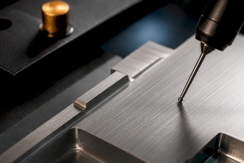
CNC surface finish is the measurable texture left on a machined part, described mainly through Ra (average roughness) and Rz (peak-to-valley height). Most general CNC parts leave the machine at Ra 3.2 µm as-machined, with finer targets of 1.6, 0.8 and 0.4 µm reserved for sealing, mating or cosmetic faces. What you actually get depends on material, tooling, machine rigidity and whether a secondary process follows.
TL;DR:
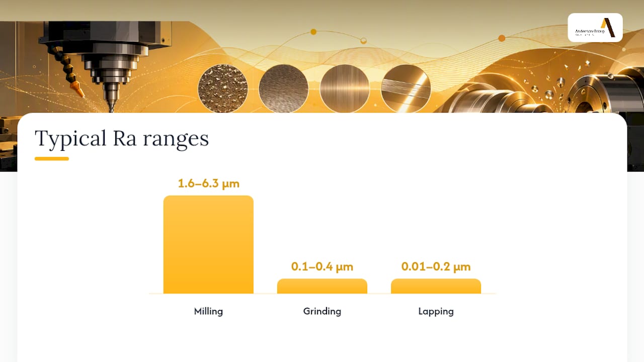
- Milling typically achieves surface finishes around Ra 1.6 to 6.3 µm, while grinding can reach Ra 0.1 to 0.4 µm, and lapping can get as low as Ra 0.01 to 0.2 µm.
- Surface finish quality relies heavily on feed per tooth, stepover, and cutting parameters, with finishing passes required for Ra below 1.6 µm.
- Tool selection and machine rigidity influence finish, where larger nose radii, coated tools, and stable fixtures help achieve lower Ra targets consistently.
- Secondary processes like anodising or plating affect dimensions and surface appearance, making it essential to specify pre- and post-finishing dimensions independently.
- For production runs, using machines designed for consistent Ra, such as Anderson’s STRATOS CNC centre, improves volume quality and reduces rework costs.
Table of Contents
- What surface finish really means: Ra, Rz, lay and appearance
- Typical Ra bands and roughness grade numbers
- How feeds, stepover and RPM change the finish
- Tooling, toolpaths and machine factors that control finish
- Material-specific guidance for common CNC materials
- How post-processing changes measured finish and dimensions
- Inspection and measurement best practice for roughness
- Specifying surface finish on drawings without overpaying
- Shop-proven capability behind these Ra targets
- A shop-floor checklist for reviewing a finish callout
- Getting the right machine behind your finish targets
- Sources
What surface finish really means: Ra, Rz, lay and appearance
Surface finish covers everything the cutting tool and any secondary process leave behind on a part, from measurable roughness to tool marks and visual texture. As Wikipedia’s overview of surface finish puts it, this includes roughness, waviness, lay and the visual effects that come with them, not just a single number on a drawing.
Two metrics dominate real-world callouts. Ra is the arithmetic average of the profile’s deviations from a centre line. It smooths out the noise, which makes it good for describing a surface’s general texture. Rz averages the peak-to-valley heights across sample lengths, so a single deep gouge or a stray burr shows up in Rz even when it barely moves the Ra number. As the surface roughness breakdown from Xometry Pro explains, this makes Rz more sensitive to isolated defects, which matters more than people assume on sealing faces.
Lay is the direction of the dominant surface pattern, set by the toolpath. It matters more than most drawings acknowledge:
- A sealing face with lay running across the seal direction will leak sooner than one with lay running parallel to it, even at identical Ra.
- Sliding surfaces (guideways, bearing bores) wear unevenly if the lay fights the direction of motion.
- Cosmetic faces can carry a “brushed” or “as-milled” note that has nothing to do with Ra at all — it is about consistent appearance, not roughness.
That last point trips up a lot of buyers. A polished-looking surface and a low-Ra surface are not always the same thing, and specifying one when you mean the other is how disputes start.
Typical Ra bands and roughness grade numbers
Most drawings still reference roughness grade numbers (N1 to N12) alongside or instead of a raw Ra value, a hangover from older drafting standards that persists because it is quick to write. Knowing how the two systems line up saves a lot of back-and-forth with the shop floor.
Process choice sets the realistic ceiling before you even talk tooling. Milling typically lands in the 1.6 to 6.3 µm range, grinding gets you to 0.1 to 0.4 µm, and lapping reaches 0.01 to 0.2 µm, according to the surface roughness guide from Geomiq. If a drawing calls for Ra 0.2 µm straight off a three-axis mill, you are asking for a grinding or lapping operation whether the drawing says so or not.
The decision rule worth memorising: specify a numeric Ra value only where it drives a function, and use a plain visual note (“as-machined” or “brushed finish”) everywhere else. Mixing the two systems freely on the same drawing is fine, but every numeric callout should earn its place.
How feeds, stepover and RPM change the finish
Surface finish is largely a geometry problem before it is a materials problem. Every rotating cutter leaves behind a scallop pattern, and the height of that scallop, not the material, is what your profilometer usually picks up first.
- Feed per tooth sets the scallop spacing along the cut direction. Halve it and you roughly quarter the theoretical scallop height, at the direct cost of cycle time.
- Stepover (the distance between adjacent passes) controls scallop height across the cut. Drop from 40% of tool diameter to 10% for a finishing pass and the visible tool marks largely disappear, though the pass count climbs sharply.
- RPM and surface speed affect finish indirectly, mostly by controlling chip load and heat at the cutting edge rather than the scallop geometry itself.
- Dedicated finishing passes with a lighter depth of cut clean up the deflection and chatter marks left by a heavier roughing pass, which is why “finish in one hit” toolpaths rarely hit tight Ra targets reliably.
Reducing feed and stepover for a finishing pass is standard practice once you are chasing anything under Ra 1.6 µm, and it is the first lever most shops pull because it needs no tooling change. As the CNC surface finish guide from CNCTAL notes, this combination of lower feed per tooth, tighter stepover and a separate finishing pass reliably lowers Ra, but it comes at the direct cost of added cycle time. That trade-off is the whole game in surface finish CNC milling: every step down in Ra band adds machine time, and somewhere around Ra 0.8 µm the cost curve starts bending sharply upward.
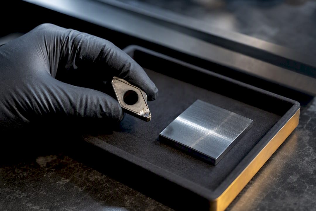
Pro Tip: Watch tool wear like it’s a live gauge, not a maintenance schedule. A worn insert or a chipped flute edge shows up in Ra readings well before it shows up as a dimensional problem, and it degrades gradually enough that operators often don’t notice until a batch fails inspection. If Ra creeps up mid-run with no parameter changes, check the tool before you check anything else.
Tooling, toolpaths and machine factors that control finish
Cutter selection is not just about geometry clearance. For finishing faces, a ball-nose cutter gives smoother blends on curved surfaces but leaves a scallop pattern that a face mill avoids entirely on flat work, while a standard end mill with a light finishing pass is often the simplest and cheapest option on prismatic parts.
A handful of tooling and machine factors decide whether that cutter selection actually delivers the finish on paper:
- Nose radius on the insert or endmill smooths the scallop crest; a larger radius generally lowers achievable Ra at the same stepover.
- Edge preparation (honed vs sharp) affects how cleanly the tool shears rather than tears the material, especially in gummy aluminium alloys.
- Coatings like TiAlN reduce built-up edge on aluminium and extend the window before wear starts degrading Ra.
- Constant scallop and morph-finishing toolpaths hold a uniform stepover across curved surfaces, avoiding the patchy finish that fixed-stepover paths leave on varying curvature.
- Machine rigidity and spindle runout set the noise floor. No feed or stepover tweak fixes a finish problem caused by a spindle running 0.02 mm out of true.
- Fixture design matters just as much. A part that flexes under cutting load will chatter regardless of how well the toolpath is planned.
Shops running heavier five-axis work, where finishing passes wrap around complex geometry, tend to notice runout and fixture stiffness issues faster because there is nowhere for a bad setup to hide.
Material-specific guidance for common CNC materials
Ra targets that are trivial in one material can be a real fight in another, and the failure modes differ enough that a single blanket spec across a multi-material assembly is usually a mistake.
- Aluminium finishes well down to Ra 0.8 µm with sharp tooling and good speeds; below that, anodising interacts with the base finish rather than masking it, so pre-finish visible faces before anodising if a premium look matters, and mask threaded or press-fit features that anodise thickness would otherwise close up.
- Carbon steel and stainless hold Ra 1.6 to 3.2 µm comfortably off the mill, but sealing-grade finishes under Ra 0.4 µm generally need grinding, and corrosion-critical stainless parts sometimes call for electropolishing rather than mechanical finishing alone.
- Plastics (nylon, acetal, PTFE) are heat-sensitive: sharp tooling, generous flute clearance and lower cutting speeds prevent the smeared, re-melted surface that ruins Ra readings on softer polymers.
- Composites need cutter geometry chosen for the fibre orientation, since delamination and fibre pull-out will wreck a finish spec no matter how well the toolpath is planned.
- Alloy and temper change the ceiling as much as the process does. A softer temper tears rather than shears, and gummy alloys will always finish worse than a free-machining grade at identical parameters.
Anderson’s metalwork CNC machinery and woodwork CNC machinery ranges are built around exactly these material-specific behaviours rather than a one-size settings sheet.
How post-processing changes measured finish and dimensions
Every secondary process changes the number on the report, not just the look of the part. Anodising and plating both add a measurable layer thickness, and that layer can telegraph the underlying tool marks rather than hide them, according to the CNC milling surface finish guide from The Supplier.
- Anodising and plating add thickness (often fractions of a millimetre to a few thousandths of an inch depending on class), which shifts critical dimensions and can amplify visible tool marks on a rough base surface.
- Bead-blasting and brushing give a uniform matte texture that hides tool marks cosmetically but generally raises Ra rather than lowering it.
- Electropolishing and mechanical polishing remove a thin surface layer, which lowers Ra but also removes material, so tight bore or thread dimensions need an allowance built in before finishing.
- Masking is non-negotiable on threads, press-fit bores and datum faces that must stay untouched. State masked areas and the required allowance on the drawing, not as a verbal instruction to the finisher.
The rule of thumb worth carrying into every design review: if a part is being anodised, plated or polished, specify the pre-finish dimension and Ra separately from the final dimension and appearance, because conflating the two is the single most common cause of finish-related rework.
Inspection and measurement best practice for roughness
Verifying a finish spec is not optional once you have paid for a tighter Ra band, and the method you choose changes what you actually catch.
- Contact profilometers (stylus instruments) remain the shop-floor default for Ra and Rz on flat or gently curved faces, and they are what most ISO-referenced reporting expects.
- Optical instruments (white-light interferometry, confocal) suit delicate, coated or curved surfaces where a stylus would scratch or skip, at higher cost per measurement.
- Sample multiple faces and orientations, not just one convenient flat, since Ra can vary meaningfully between a milled face and an adjacent drilled bore on the same part.
- Take readings perpendicular to lay wherever possible, since measuring along the lay direction can understate the true roughness.
- Reference ISO 1302 conventions for how the value is reported on the drawing, so the number on the inspection sheet matches what the designer intended.
The most common pitfall is measuring a convenient face instead of the functional one because it is easier to reach with a stylus. It produces a clean-looking inspection report that says nothing about the surface that actually matters.
Specifying surface finish on drawings without overpaying
A drawing full of tight Ra callouts on every face is a cost driver, not a quality signal. Good practice is narrower and cheaper.
- Specify a numeric Ra value only on faces where it does real work: seals, bearing bores, sliding fits, optical or cosmetic-critical surfaces.
- Use a plain visual note (“as-machined”, “bead-blast matte”) everywhere else instead of defaulting to a low Ra out of caution, a point echoed in Geomiq’s surface roughness guide.
- State coating thickness and the post-finish dimension separately from the pre-finish machined dimension wherever anodising, plating or polishing is involved.
- Call out lay direction explicitly on sealing and sliding faces, since two surfaces with identical Ra but different lay perform very differently in service.
- Talk to the shop before you finalise tolerances. Anderson’s guide to CNC tolerances tied to ISO 2768 is a useful check on how finish and dimensional tolerance interact before a print goes final.
- Never apply a blanket low-Ra requirement across an entire part “to be safe.” It is the single easiest way to blow a quote out for no functional gain.
Shop-proven capability behind these Ra targets
Anderson has built and serviced CNC machining equipment since 1972, across woodworking, metalworking and advanced materials, which means the finish guidance above is grounded in equipment actually running these jobs, not theory.
- Machine rigidity, spindle quality and fixture options directly set the finish ceiling discussed earlier, and Anderson’s MASS-B enclosed 5-axis machine and MASS-5 large-scale 5-axis centre are built for exactly the tight-tolerance, complex-geometry work where finish control matters most.
- The STRATOS CNC machining centre suits shops running higher-volume production where consistent Ra across a batch matters as much as hitting the number once.
- As a practical example: a part needing Ra 0.4 µm sealing faces on a curved geometry points toward a rigid 5-axis platform with morph-finishing toolpaths, not a light-duty router pushed past its comfort zone.
A shop-floor checklist for reviewing a finish callout
Before anything goes to the machine, I run the same short pass on a drawing every time. First, find every numeric Ra callout and ask whether it sits on a genuinely functional face. If it does not, it gets flagged for a visual note instead. Second, check masking is called out wherever anodising or plating follows machining. Third, confirm the fixture plan and tool condition actually support the target, because a tired insert or a soft clamp will undercut the best toolpath on paper.
The go/no-go rule is simple: if the drawing asks for anything under Ra 0.8 µm on a mill-only process plan, that is a conversation before it is a job. Either the process plan needs grinding or polishing added, or the callout needs revisiting.
— Scott
Getting the right machine behind your finish targets
Anderson gets you closer to your target Ra straight off the machine, which cuts the finishing work you’d otherwise pay for downstream. The right machine and tooling combination controls scallop height and chatter at the source, rather than relying on a secondary polishing or grinding step to fix what the mill left behind.

That matters most on production runs, where a machine that holds Ra 1.6 µm consistently across a thousand parts saves far more than one that hits it occasionally and needs rework on the rest. The STRATOS CNC machining centre is built for exactly that consistency at volume, with the rigidity and spindle quality that keep scallop height predictable pass after pass. If you are specifying finishes on parts that need to hit a band reliably rather than occasionally, get in touch with Anderson to talk through machine selection for your process plan and see the STRATOS specifications for your production targets.
Sources
- Surface finish — Wikipedia
- What are the types of surface finishes for CNC machining? — Hubs knowledge base
- CNC Machining Surface Roughness: Indicators & Levels — Xometry Pro
- CNC machining surface finish guide — CNCTAL