
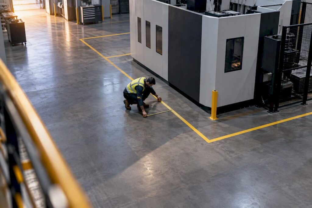
Budget a footprint of roughly 3.5 m × 4 m for a small industrial CNC unit up to around 7 m × 10 m for a large horizontal machining centre, then add clearance on top. Reserve a minimum of 1 metre of access space on every service side, and multiply the vendor’s stated footprint by around 1.4 to cover circulation and material handling. Before locking your layout, confirm the actual service envelope and utility connection points with the machine supplier.
TL;DR:
- Reserve at least 40% more space than the vendor’s footprint to account for access, circulation, and material handling around the machine.
- Ensure the ceiling height exceeds 3.5 meters to accommodate tool changers, ductwork, and overhead cranes within the cell.
- Size aisles based on the longest handled load and forklift turning radius, with main aisles at 3.6–4.5 meters to prevent bottlenecks.
- Allocate 800–1,200 millimeters of clearance on primary maintenance sides, and keep crane paths free for major component servicing.
- Conduct a floor mock-up walkthrough and verify utility, foundation, and space requirements before installing the machine to avoid costly adjustments later.
Table of Contents
- Typical CNC machine footprints and clearance envelopes
- Power, air, coolant and extraction: what the site needs before delivery
- How wide do CNC workshop aisles and crane bays need to be?
- What maintenance and service clearance do you actually need?
- Pre-installation checklist: what to verify before the machine arrives
- Matching machine size to your parts, tolerances and throughput
- Where CNC layout planning actually goes wrong
- Getting your site assessed before you commit to a layout
- Sources
- FAQ
Typical CNC machine footprints and clearance envelopes
The number on a vendor’s spec sheet is the machine footprint, not the floor you need to reserve. That figure covers the base and columns, nothing else. The real installed envelope includes swing arcs, chip conveyors, pallet changers and the walking space a technician needs to open a panel without bumping into the next cell.
Small vertical machining centres typically need about 3.5 m × 4 m of installed area, while large horizontal machining centres can run up to roughly 7 m × 10 m once you account for pallet pools and conveyor runs. Ceiling height matters too. Most industrial CNC cells need 3.5–4 m of clear height above the machine for tool changers, chip evacuation ductwork and any overhead crane sweep.
A workable rule of thumb: take the vendor’s footprint and add around 40% for access and circulation, a ratio plant layout planning backs consistently across facility types. When you review the vendor drawing, check specifically for:
- Chip conveyor discharge path and bin clearance
- Pallet changer swing radius on APC-equipped machines
- Door swing arcs on enclosed 5-axis cells
- Electrical cabinet access panel, usually on the rear or side
- Coolant tank service access, often underestimated in early layouts
Power, air, coolant and extraction: what the site needs before delivery
Industrial CNC centres run on 415 V three-phase power, with draws ranging from around 15 kVA for smaller units up to 50 kVA for larger horizontal centres. Every installation must comply with AS/NZS 3000 (electrical wiring standards), and your electrical contractor should size the switchboard and cabling against the machine’s actual nameplate draw, not a rough estimate.
Compressed air sits in the 6–8 bar range for most tool-change and clamping functions, fed through a dedicated line rather than a shared shop feed prone to pressure drops. Coolant and extraction provisions depend on the material you’re cutting: metalworking needs mist or flood coolant capture, while composites and advanced materials need dedicated dust extraction sized to the cutting head.
Foundation work matters more than most planners expect:
- Reinforced concrete slabs of around 300 mm thickness suit heavier machining centres
- Levelling pads and vibration isolation protect tolerance-critical work
- Maintain ambient temperature between 20°C and 26°C for accuracy-sensitive operations
- Site AS/NZS 4024 (machine safety standards) reviews alongside guarding and interlock design, not as an afterthought
How wide do CNC workshop aisles and crane bays need to be?
Aisle widths and crane coverage should be sized from your worst case, not your average day. A single 6-metre bar stock or an oversized fixture pallet dictates the turning geometry every forklift on that route will need, so plan around the longest load you’ll actually handle rather than typical traffic.
- Set main aisles carrying two-way forklift traffic at 3.6–4.5 m, wide enough for simultaneous opposing movement without a stop-and-wait bottleneck.
- Set secondary aisles, used for occasional access rather than through traffic, at 2.4–3.0 m.
- Calculate required aisle width from your forklift’s turning radius plus the longest handled load length, then add a safety margin rather than relying on a generic standard.
- Size overhead crane capacity for the heaviest single lift your shop performs. Many small to mid-size shops get by with a 3 to 5 tonne bridge crane.
- Set runway setbacks so the crane’s hook coverage genuinely reaches every machine bay that needs it, including the far corner where a spindle swap might happen years after installation.
Skipping the worked-example step is the most common aisle-planning mistake. Planners size aisles from average pallet traffic, then discover the one oversized casting or long extrusion that arrives twice a year simply doesn’t fit.
What maintenance and service clearance do you actually need?
Not every side of a machine needs the same clearance, and treating them all equally wastes floor space you probably don’t have. Categorise access by how often a technician actually needs it.
Daily tasks (chip removal, coolant top-up, tool changes) need the fastest, least obstructed path. Weekly and quarterly tasks (filter changes, way lubrication checks) can tolerate a slightly tighter but still walkable zone. Annual or major component work (spindle replacement, ballscrew service) can sit in a more constrained space, provided a crane or removal path can still reach it without relocating the machine.
- Reserve 800–1,200 mm at primary maintenance sides where daily and weekly tasks happen
- Keep a dedicated crane or rigging path clear for major component removal, even if it doubles as walkway space most of the year
- Route utility drops through quick disconnect couplings rather than fixed hard plumbing, so a cell can be serviced or repositioned without a re-plumb
- Orient service-heavy panels toward the aisle, not the wall, wherever the machine’s design allows it
Pro Tip: Rank your maintenance tasks by frequency before you finalise layout, not after. A cell that’s brilliant for daily chip removal but blocks the annual spindle service crane path will cost you a production day the first time that service comes due.
Pre-installation checklist: what to verify before the machine arrives
A floor mock-up catches more layout problems than any drawing review, because walking a masking-tape outline reveals swing arcs and pinch points a 2D plan misses entirely.
- Confirm slab thickness, reinforcement and levelling tolerance match the machine’s foundation spec.
- Verify crane coverage and forklift access reach every point the machine will need serviced or resupplied.
- Confirm electrical termination points, kVA capacity and AS/NZS 3000 compliance sign-off.
- Confirm compressed air line pressure, capacity and dedicated routing to the cell.
- Mark out the full footprint plus service envelope on the actual floor using tape, then walk the maintenance tasks physically.
- Schedule rigging, installer sign-off, operator training and safety interlock checks ahead of first power-on.
Matching machine size to your parts, tolerances and throughput
The work envelope you need starts with your largest part, not your average one. If you’re occasionally running a part that pushes the X or Y travel limit, that outlier should govern the machine spec, because undersizing here means turning down work later.
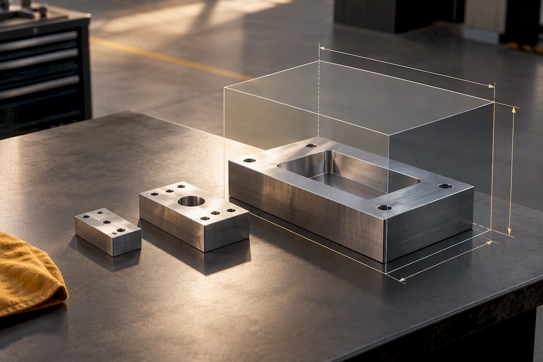
Tolerance band is the second input, and it has a direct floor-space consequence: tighter tolerances demand more rigid foundations, better vibration isolation and tighter environmental control, all of which widen the footprint you need to reserve around the machine, not shrink it. A shop chasing ±0.13 mm tolerances tied to ISO 2768 needs a fundamentally different foundation plan than one running rough structural work.
Throughput targets bring peripheral equipment into your space budget:
- Bar feeders extend the machine’s physical length, sometimes by several metres
- Pallet pools need their own footprint plus load and unload clearance
- Inspection stations near the cell reduce work-in-progress travel but add floor demand
- Automated material queues for nesting-first workflows need buffer space the machine spec sheet never mentions
Where CNC layout planning actually goes wrong
The three mistakes I see most often on site visits are restricted service access, undersized aisles, and utilities routed to the wrong side of the machine. All three are cheap to fix on paper and expensive to fix after the slab is poured. Walk the maintenance tasks on a taped mock-up before you sign off. Anderson’s Shop Floor Playbook case studies on waste reduction show this single step catches most layout errors early.
— Anderson
Getting your site assessed before you commit to a layout
CNC machining centres for wood, metal, and advanced materials often come with a site assessment before delivery to help ensure proper fit and installation. That’s the real difference for a planner staring at a vendor drawing and trying to guess whether your slab, your crane, and your aisles will actually work: you get someone checking the fit before the equipment leaves the factory floor, not a generic spec sheet you have to interpret yourself.

If you’re speccing a new cell, request Anderson’s Shop Floor Playbook and installation checklist alongside a site survey. It covers the same clearance, utility, and foundation questions this guide raises, applied to your actual floor and your actual machine choice. Browse the metal machining centres or wood machinery range to shortlist a configuration, or go straight to the full machine lineup and request a quote against your site’s dimensions today.
Sources
- CNC horizontal machining centre prices in Australia: complete buying guide
- Best practices for manufacturing plant layout design: a complete guide
- Machine shop layout planning reference for 3100 SF – Industrial Monitor Direct
- Space-saving CNC manufacturing for easy maintenance
FAQ
How much floor space does a small CNC machine need?
A small industrial CNC unit typically needs around 3.5 m × 4 m of installed floor area, plus at least 1 metre of clearance on every service side.
What electrical supply does an industrial CNC centre need?
Most industrial CNC machining centres run on 415 V three-phase power with draws between 15 kVA and 50 kVA depending on size, and every installation must meet AS/NZS 3000 (electrical wiring standards). Confirm the exact draw with your machine supplier before sizing the switchboard.
How wide should aisles be for CNC workshop layout?
Main aisles carrying two-way forklift traffic need 3.6–4.5 m of clearance, while secondary aisles for occasional access can run 2.4–3.0 m. Size both from your longest handled load and your forklift’s turning radius, not average traffic.
How much clearance do I need for CNC machine maintenance?
Reserve 800–1,200 mm at primary maintenance sides where daily and weekly service tasks happen, and keep a dedicated crane or rigging path clear for major component removal. Prioritise clearance by task frequency rather than treating every side of the machine equally.
Does Anderson Group Australia help with CNC site layout planning?
Yes. Anderson Group Australia offers site assessments alongside its machine supply for wood, metal and advanced materials machining centres, checking slab, utilities and clearances against your actual floor before delivery. Current pricing for specific machine lines is available on request through the machine lineup page.