
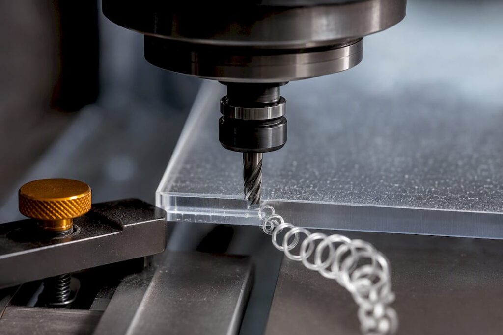
Polycarbonate can be machined with a process selected for its grade, geometry and required finish. Confirm tooling, workholding, cooling and chemical compatibility with the material and machine suppliers, then validate the result on representative material.
TL;DR:
Precise control of heat, chip evacuation, and using sharp carbide tools are essential for clean polycarbonate cuts and maintaining optical clarity.
Use low-flute-count cutters and avoid petroleum-based lubricants to prevent melting and stress cracking during machining.
Select dry or wet processing and any coolant from the material manufacturer’s guidance for the specific grade and operation.
Thin unsupported sheets are prone to flexing; vacuum fixturing and careful toolpath planning minimize chatter and dimensional inaccuracies.
Heavy machining warrants annealing at around 120°C to relieve internal stresses and ensure dimensional stability and optical quality.
Table of Contents
-
Is polycarbonate machinable: material properties and practical limits
-
Feeds, speeds and cut engagement: calculating RPM, feed per tooth and cut depth
-
Cooling, lubrication and heat control: what to use and what to avoid
-
Workholding, fixturing, toolpaths and CAM strategies for thin or flexible stock
-
Finishing: deburring, polishing and protecting optical surfaces
-
Dimensional behaviour, annealing and tolerances for accurate parts
-
Occupational safety, particulates and emissions controls when machining PC and composites
-
Post-machining treatments, including stress relief methods beyond annealing
-
Perspective: when to machine polycarbonate in-house vs outsource
-
How Anderson Group Australia helps with polycarbonate machining needs
-
Selected technical data sheets, standards and regulator guidance
Is polycarbonate machinable: material properties and practical limits
Polycarbonate machines well on the same three, four and five axis centres used for aluminium and engineering plastics, provided the shop respects its thermal behaviour. The material’s high impact resistance is an asset in service but a liability at the cutter: it resists chip shear more than acrylic does, which pushes heat into the tool and the part rather than into a clean break. Glass transition temperature sits low enough that sustained rubbing or dull edges can soften the surface before the operator notices anything wrong on the spindle load meter.
Reinforced and filled grades change the equation further. Glass-filled or flame-retardant polycarbonate blends cut more like a composite: abrasive fillers wear tool edges faster and can raise particulate output, a point picked up later in the safety section.
-
Sheet stock under 6 mm machines readily on standard routers and mills with light DOC passes.
-
Thicker sheet and rod (10 to 25 mm) need more attention to chip clearance and cooling.
-
Extruded tube sections often need internal support or mandrels to avoid ovaling under clamping load.
Compared with acrylic, polycarbonate is tougher and less prone to cracking under load but more prone to melting and stringing if feeds are too slow. Shops moving between the two materials, a common pairing in signage and enclosure work, benefit from treating them as separate parameter sets rather than variations on one recipe, a topic covered in more depth in a guide to CNC machining acrylic.
Choosing cutters and tooling geometry for polycarbonate
Sharp carbide-tipped tooling is the single biggest factor separating a clean cut from a melted one. Makrolon® technical guidance is explicit on this point: use sharp carbide tools and keep them that way, because a dulling edge generates friction heat long before it fails to cut.
Flute count matters more for plastics than for metals. Fewer flutes, typically one or two, leave more gullet space to clear the long, stringy chips polycarbonate tends to produce. Three or more flutes pack chips into the cut, and that trapped material is what melts and re-welds to the tool and the part wall.
-
Single or double flute “O flute” style cutters suit roughing and general profiling.
-
Ball nose endmills suit 3D contours where a rounded finish is needed.
-
Bull nose or corner-radius cutters reduce chipping at part edges on thin sheet.
-
Straight flute cutters with a polished flute face help chip ejection on deep pockets.
Coatings are a judgment call. A coating that raises thermal tolerance can also round off the cutting edge slightly, and for plastics that trade-off often works against you. Advanced CNC milling guidance notes that carbide alone tolerates higher surface speeds than HSS without needing a coating, and an uncoated, freshly grounded edge is often the better choice for polycarbonate specifically. Inspect edges under magnification every few jobs, since a tool that still looks fine to the naked eye can already be rubbing rather than cutting.
Pro Tip: Keep a dedicated set of cutters for plastics only. Sharing tooling with aluminium or steel jobs dulls the edge faster than most shops expect.
Feeds, speeds and cut engagement: calculating RPM, feed per tooth and cut depth
Feeds and speeds for polycarbonate start from the same formulas used across CNC milling generally, then get pulled toward the conservative end. UNSW’s feeds and speeds resource gives the two core calculations:
-
RPM equals surface speed multiplied by 318.06, divided by tool diameter.
-
Feed rate equals RPM multiplied by feed per tooth multiplied by number of flutes.
Say a 6 mm two flute carbide endmill is targeting a surface speed suited to plastics. Plugging that diameter into the RPM formula, then applying a feed per tooth in the light, chip-clearing range typical for softer plastics, gives a starting feed rate that a CAM operator then dials in against real cutting behaviour rather than treating as fixed. The same source stresses that documented test cuts, not generic published tables, are what make feeds and speeds repeatable in a real shop, since spindle rigidity, tool run out and stock thickness all shift the ideal number.
Depth of cut and width of cut follow a similar logic to aluminium roughing, scaled down. Roughing passes on polycarbonate typically stay shallower than an equivalent pass in soft aluminium to keep chip volume manageable, while finishing passes take a light, high-speed skim to avoid re-cutting softened material.
Particle-exposure measurements do not establish machining-temperature performance. Assess contaminant control and process cooling separately; do not transfer a percentage from another material or drilling setup to this application.
The tuning process is iterative: run a test cut, stop, inspect the chip. A tightly curled, cool-to-the-touch chip means the parameters are close. A melted, stringy or discoloured chip means the feed is too slow, the RPM too high, or the tool is dull, and the fix is to adjust one variable at a time and re-test before committing to a full job.
Cooling, lubrication and heat control: what to use and what to avoid
Polycarbonate can be sensitive to contact with incompatible chemicals. Check the grade-specific fabrication and chemical-resistance guidance before selecting a cutting fluid. Manufacturer guidance such as Plaskolite’s TUFFAK MG fabrication sheet addresses particular products and operations, not every polycarbonate grade.
Use a cooling method approved for the grade, operation and machine. Do not assume that water, compressed air or a liquid coolant is suitable merely because it is used on another plastic.
-
Confirm the coolant’s compatibility with the material supplier before use.
-
Evaluate any wet-machining proposal for cooling, exposure control, equipment compatibility and waste handling.
-
Direct air nozzles at the cut zone, not just the tool shank, to clear chips as they form.
-
Use pulsed air and shorter passes rather than one long continuous pass on thick sections.
-
Retract the tool periodically on deep pockets to let trapped heat dissipate before continuing.
Workholding, fixturing, toolpaths and CAM strategies for thin or flexible stock
Thin polycarbonate sheet flexes under clamping and cutting forces in a way that solid aluminium billet never does, and that flex is what causes chatter, poor tolerance and inconsistent finish. Vacuum tables with a sacrificial MDF or plastic backerboard are the standard fix, giving even support across the full sheet rather than the point loads a mechanical clamp creates. Tabs left uncut until a final separation pass, or light double-sided adhesive on small parts, keep offcuts from lifting mid-job.
Climb milling is generally preferred over conventional milling for plastics, since it tends to produce a cleaner shear rather than the tearing action conventional milling can leave on a soft edge. UNSW’s CAM and tooling guidance also notes that toolpath choice itself changes heat generation, not just tool selection.
-
Adaptive or trochoidal roughing spreads chip load evenly and suits large-volume removal.
-
Small step-over finishing passes suit optical or cosmetic surfaces where scallop marks matter.
-
Leave 0.2 to 0.5 mm of stock for a dedicated finishing pass rather than roughing to final size.
-
Support unsupported spans with sacrificial webbing until the final separation cut.
Pro Tip: Run finishing passes at a lighter DOC and slightly higher feed than roughing. It keeps the tool cutting rather than rubbing across an already-formed surface.
Drilling, tapping and fastening through polycarbonate
Holemaking is where cracking risk concentrates, because drill point geometry and axial force both push directly against the material’s tendency to craze under stress.
-
Use a drill point angle around 90 to 100 degrees rather than the sharper angles common for metal, to reduce the wedging action that starts cracks.
-
Peck drill on anything past a few millimetres deep, retracting fully every few millimetres to clear chips and let heat dissipate.
-
For threads, prefer thread inserts such as Helicoil or PEM inserts over cutting threads directly into polycarbonate, since inserts distribute load and resist stripping far better than a tapped plastic thread.
-
Chamfer every drilled hole edge and avoid sharp internal corners on bosses, since stress concentrates exactly at those points.
-
Where a part will be annealed after machining, drill holes very slightly oversize to allow for the small dimensional shift annealing can introduce.
Finishing: deburring, polishing and protecting optical surfaces
Where a part needs to stay optically clear, the protective PE film should stay on for as much of the machining process as possible. Makrolon guidance recommends leaving masking in place to prevent surface scuffing, and warns against long UV exposure of that film since the adhesive can harden and become difficult to remove cleanly.
-
Deburr edges mechanically with a fine file or scraper before any polishing step.
-
Work through progressively finer polishing pastes for a true optical finish rather than jumping straight to a fine grit.
-
Flame polishing can restore clarity to a cut edge but requires careful control to avoid localised melting or discolouration.
-
Chemical polishing with solvent vapour is an option for some grades but needs proper ventilation and is not suited to every polycarbonate formulation.
-
Inspect final parts under raking light to catch fine scratches that are invisible under normal lighting.
Dimensional behaviour, annealing and tolerances for accurate parts
Polycarbonate expands and contracts more than metal does across a working temperature range, and Makrolon technical data puts the coefficient of linear thermal expansion at around 0.065 mm per metre per degree Celsius. Over a 500 mm part and a modest workshop temperature swing, that is enough movement to matter for tight-tolerance assemblies.
-
Anneal heavily machined parts, with Makrolon’s own guidance pointing to roughly 120°C for a period set by wall thickness, to relieve internal stress before final inspection.
-
Measure critical dimensions at a stable room temperature rather than straight off the machine.
-
Design mating metal parts with clearance that accounts for polycarbonate’s greater thermal movement, particularly on snap fits and press fits.
-
Treat published tolerances as a starting point and confirm against your own annealed, room-temperature parts before locking in a production spec.
Occupational safety, particulates and emissions controls when machining PC and composites
Assess the dust, vapour and other contaminants generated by the exact material and process, especially where fillers or coatings are present. Select controls through the site assessment rather than extrapolating a test result from a different composite.
-
Fit local exhaust ventilation or on-tool extraction at the cut zone rather than relying on general workshop airflow.
-
Confirm any wet-machining method and collection arrangements with the material and equipment suppliers and responsible safety specialist.
-
Match filtration media to the fine particulate sizes plastics and composites generate, not just wood dust settings, a distinction covered in the wood dust standards checklist.
-
Log extraction system checks and PPE use as part of routine maintenance, since particulate exposure risk changes with tooling and material batch.
-
Confirm local council or environmental reporting obligations for any non-scheduled machining activity that generates dust or emissions.
Common failure modes and troubleshooting guide
Melting, stringing chips and a glassy, discoloured cut edge are the clearest signs something is wrong before a part is even off the machine.
-
A melted or welded chip means the feed is too slow relative to RPM: increase feed per tooth first before changing anything else.
-
Built-up edge on the tool, visible as a whitish residue, calls for a sharper tool or a lower flute count to improve chip clearance.
-
Chatter marks on thin sheet point to inadequate workholding rather than a cutting parameter problem.
-
Stress-whitened areas around holes or edges suggest annealing is needed before the part goes into service, or the batch should be scrapped if cracking has already started.
-
Before any cut, confirm tool sharpness, coolant plan and fixturing are all set correctly rather than troubleshooting mid-job.
Practical workshop notes from Anderson Group Australia
Machine rigidity and spindle behaviour change what is achievable with polycarbonate more than most operators expect. A stiffer frame and a well-damped spindle keep chatter down on thin sheet, which matters more for plastics than raw horsepower alone.
-
Enclosed machining centres help contain fine plastic particulate before it reaches the workshop floor.
-
Auto pallet changing (APC) suits shops running repeat polycarbonate parts where consistent fixturing matters.
-
Dust extraction compatibility across a machine’s enclosure is worth checking against your extraction system’s rated airflow, not assumed.
Anderson Australia supplies CNC machinery, servicing and spare parts for woodworking, metalworking and advanced-material applications. Confirm machine suitability for the specific polycarbonate grade, part geometry and production process with the team.
Post-machining treatments, including stress relief methods beyond annealing
Annealing is the best-known stress relief step for machined polycarbonate, but it is not the only lever available, and combining approaches often produces a more stable part than annealing alone.
Slow, controlled cooling after any thermal process reduces the risk of new stress forming as the part returns to room temperature, so parts should rest undisturbed rather than being handled or fixtured again immediately after an oven cycle. Vapour or solvent treatments used in some finishing workflows can also relieve surface-level stress on cut edges, though they need to be matched to the specific polycarbonate grade since not every formulation responds the same way to solvent exposure.
Mechanical stress relief, achieved simply by machining in lighter passes with more finishing steps rather than one aggressive roughing cut, reduces the internal stress introduced during cutting in the first place, which lowers the annealing burden needed afterward. For parts destined for outdoor or UV-exposed service, a light post-machining inspection under polarised light can reveal residual stress patterns invisible to the naked eye, letting a shop catch a problem part before it reaches assembly rather than after it cracks in the field.
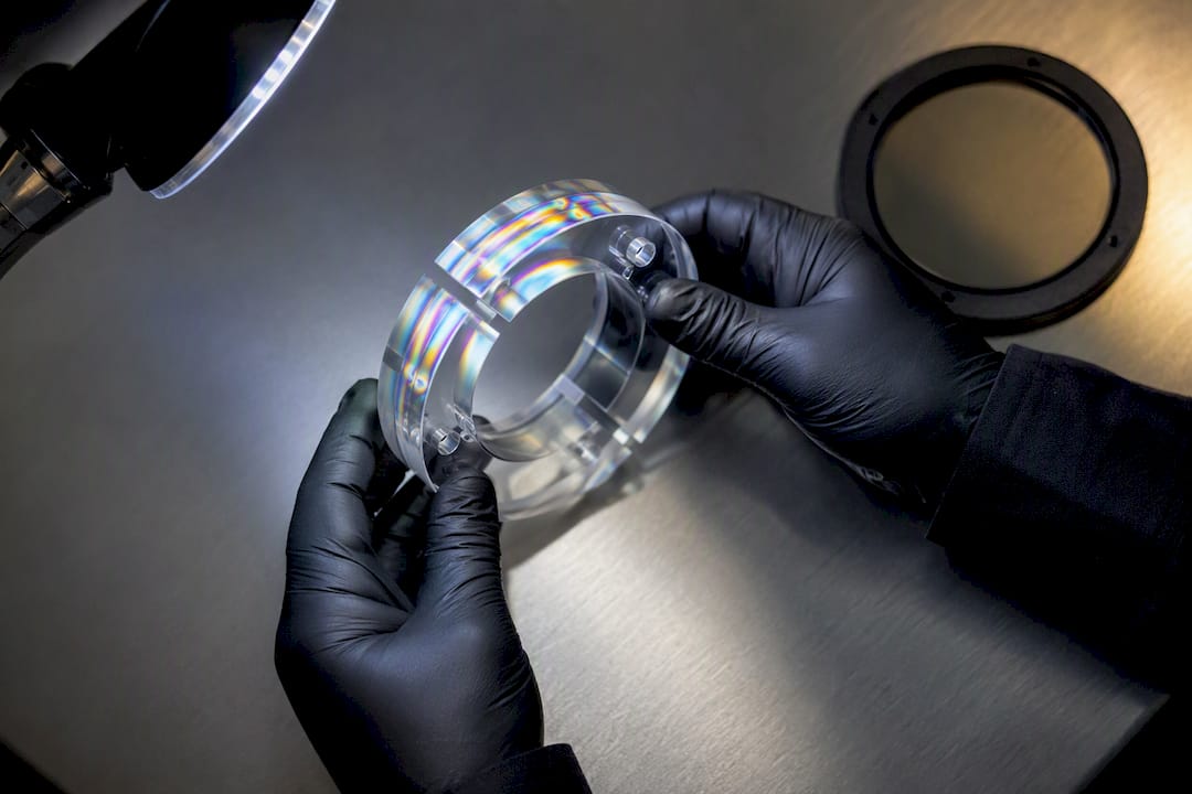
None of these steps replace annealing for heavily machined parts. They sit alongside it, and the combination of gentler cutting parameters plus a proper anneal schedule is what keeps dimensionally critical or optically clear parts stable over their service life.
Comparison of polycarbonate machining vs. other plastics
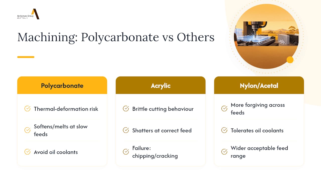
Polycarbonate sits in a different parameter band to most other machinable plastics, and shops that treat all plastics the same tend to get inconsistent results.
Acrylic cuts more like a brittle material: it shatters cleanly at the right feed rather than melting, and its main failure mode is chipping or cracking rather than thermal deformation. Polycarbonate is the opposite case: it resists cracking well but softens and melts readily if feeds are too slow, which is why Makrolon’s own guidance frames thermal deformation, not hardness, as the primary machining challenge for the material.
Different plastic grades have different machining and chemical-compatibility requirements. Use the relevant supplier’s material information rather than treating one plastic’s coolant or emission controls as suitable for another.
Keep a validated process record for each material grade and part family. Changes in tooling, cooling or machining parameters should be assessed and trialled before production.
Design considerations to optimise polycarbonate machinability, including tolerances and wall thickness
Good part design removes half the machining problems before the job ever reaches the spindle.
Wall thickness is the first lever. Thin unsupported walls under roughly 2 mm flex under cutting force and clamping pressure, which drives chatter and dimensional drift regardless of how well the feeds and speeds are tuned. Where a design allows it, ribbing or local thickening at load points reduces flex without adding much material cost.
Tolerances should account for polycarbonate’s thermal expansion rather than borrowing a metal-part tolerance table directly. A tight press fit designed for aluminium can bind or crack in polycarbonate once ambient temperature shifts, given the material’s coefficient of linear thermal expansion. Snap fits and mating features benefit from slightly generous clearance and a radius at stress points rather than a sharp internal corner.
Boss and hole placement matters too: keeping fastener bosses away from sheet edges and giving them a chamfered lead-in reduces the crack initiation risk covered earlier in drilling. Where a design calls for a fully clear, optical-grade surface, it pays to plan the toolpath and finishing allowance at the CAD stage rather than leaving it to be resolved on the shop floor, since a finishing pass sized too small will not remove the tool marks a roughing pass leaves behind.
Perspective: when to machine polycarbonate in-house vs outsource
The decision to bring polycarbonate machining in-house rather than outsourcing it comes down to run volume, finishing needs and how much safety infrastructure you are already carrying. A shop running occasional prototype parts rarely justifies the extraction and fixturing investment polycarbonate deserves, and contract machining is the more sensible route until volume climbs.
Where automation pays off is repeat production: auto pallet changing and enclosed machining centres earn their cost once a shop is running the same polycarbonate part, or family of parts, often enough that setup time and particulate handling become recurring costs rather than one-off considerations. At that point, the calculation shifts from “can we cut this” to “can we cut this consistently, safely, and without babysitting every pass,” and that is a capital equipment question rather than a technique question.
Matching a machine to a job profile, rather than buying the most capable machine available, is usually the more defensible decision, and it is the question worth answering honestly before signing off on any purchase.
How Anderson Group Australia helps with polycarbonate machining needs
Manufacturers moving polycarbonate work in-house need a machine that handles thermal-sensitive plastics as confidently as it handles aluminium or steel, and that is where the right equipment choice changes the outcome more than any single cutting parameter.

Compare Anderson Australia’s advanced materials machinery range against the polycarbonate grade, sheet or billet dimensions, part geometry and production volume. Shops working with other materials can also review the wood machinery range and metal machinery range. Confirm the exact machine configuration, workholding, enclosure and extraction requirements with the supplier before ordering.
-
Enclosed centres help contain fine particulate generated when machining polycarbonate and its composites.
-
APC-equipped machines reduce setup time on repeat polycarbonate production runs.
-
5-axis platforms suit complex optical or contoured polycarbonate geometry in one setup.
For a machinery enquiry, provide your material grade, drawings, thickness range, required finish and target output. Anderson Australia supplies machinery, servicing and spare parts; it does not provide subcontract cutting or machining. Confirm the availability and scope of application checks directly with the team.
Selected technical data sheets, standards and regulator guidance
The technical constants and machining tables referenced through this guide come from named, checkable sources rather than generic advice.
-
Makrolon® solid polycarbonate technical data for thermal expansion, annealing and tooling guidance.
-
MISCO Australia’s polycarbonate product notes for supplier-level machinability and finishing information.
-
Safe Work Australia’s composite machining emissions report for particulate control evidence.
-
UNSW’s CNC feeds and speeds resource for the RPM and feed rate formulas used above.
Sources
FAQ
Is polycarbonate machinable on standard CNC equipment?
Yes, polycarbonate machines well on standard CNC mills and routers once feeds, speeds and cooling are set to avoid melting. MISCO Australia describes polycarbonate as offering excellent machinability alongside strong optical clarity in clear grades.
What is the hardest metal to machine, and how does that compare to polycarbonate?
Among metals, superalloys and hardened tool steels are typically the most difficult to machine due to their hardness and heat resistance, a very different challenge from polycarbonate. Polycarbonate is not hard to cut in that sense: its main challenge is thermal sensitivity rather than resistance to the cutting edge.
What is the best tool to cut polycarbonate?
Sharp carbide-tipped cutters with a low flute count, one or two flutes, work best for polycarbonate because they clear chips efficiently and avoid the friction heat that dull or high-flute-count tools generate. Makrolon’s technical guidance specifically recommends sharp carbide tooling for this reason.
Can you cut polycarbonate with a CNC router or mill?
CNC routers or mills may be suitable when the exact machine, tooling and process match the polycarbonate grade and required part. Follow grade-specific fabrication guidance and validate cooling and chemical compatibility.
Does polycarbonate need annealing after machining?
Heavily machined polycarbonate parts often benefit from annealing to relieve internal stress, with Makrolon’s guidance pointing to a temperature around 120°C for a period set by part thickness. Lightly machined or thin parts may not need it, but tight-tolerance or heavily drilled parts usually do.