
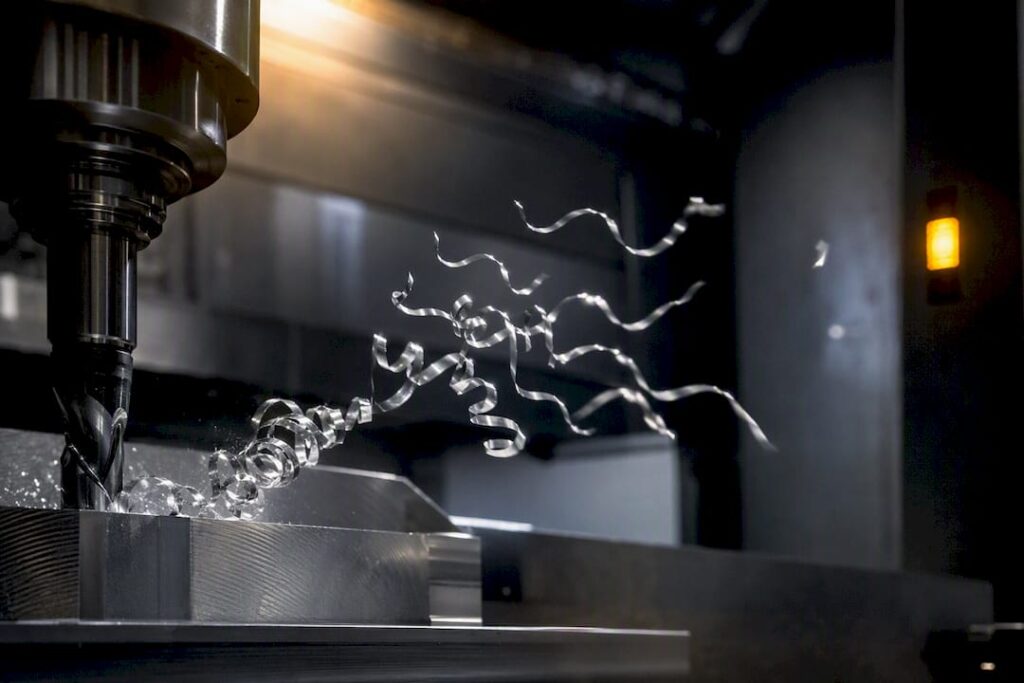
The most effective way to stop chip related failures in aluminium is to pair the right cutter geometry with aggressive directed flushing or air, then program toolpaths that never let flutes pack solid. That combo, a few flute high helix cutter with a large gullet, high pressure coolant or air aimed at the exit, and trochoidal or adaptive passes, cuts built up edge and recutting almost immediately. Shops that make this switch typically see longer tool life and cleaner finishes within the first job.
TL;DR:
- Using cutter geometries with high helix angles, aggressive flushing, and trochoidal or adaptive toolpaths significantly reduces chip buildup and increases tool life during aluminum milling.
- Proper coolant pressure of at least 15 bar and nozzle placement directly at the flute exit are essential for effective chip evacuation, especially in high-speed, deep cut applications.
- Selecting the correct flute count, helix angle, and coating, such as polished carbide or DLC, can prevent aluminum from sticking and improve cutting speeds without buildup issues.
- Overspecifying machine systems, including conveyors sized at roughly double the peak chip volume and high-pressure coolant pumps, prevents chip accumulation and maintains continuous production.
- Monitoring for warning signs like increased spindle noise or chip discoloration enables operators to address packing issues early and adjust toolpaths or replace worn tools before failure.
Table of Contents
- Chip evacuation aluminium starts with cutter geometry
- Coolant and air delivery that actually clears the flute
- Toolpath tactics that keep flutes from packing solid
- Machine systems that carry chips the rest of the way
- Reading the warning signs before a tool breaks
- What system upgrades actually fix at production scale
- A shop engineer’s take on chasing chip control
- How Anderson helps you fix chip evacuation at the machine level
- Where to go deeper on chip evacuation
- Sources
Chip evacuation aluminium starts with cutter geometry
Get the tool wrong and no amount of coolant will save you. Aluminium produces long, stringy, gummy chips that want to weld themselves to a hot flute, so the cutter’s job is to lift and eject that chip before it has a chance to recut.
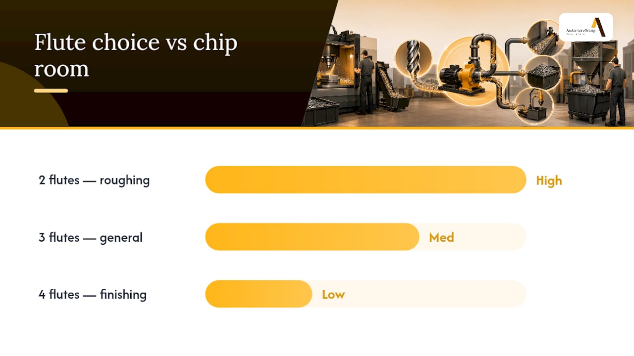
Flute count is the first decision. Two flutes give you the most chip room and suit heavy roughing or slotting where evacuation matters more than surface finish. Three flutes are the workhorse for general aluminium milling, balancing chip clearance against a smoother wall finish, and HMN Tool’s chip evacuation guide treats the 3-flute as the default choice for most aluminium work. Four flutes only make sense on finishing passes with light radial engagement, because the tighter gullets choke on anything heavier.
Gullet volume and core diameter fight each other. Helix angle is also important; angles in the range often recommended for aluminium work efficiently lift chips out, and variable helix designs help reduce chatter and harmonic vibrations during heavier cuts.
Coating choice trips up a lot of machinists moving from steel work. Coatings built for ferrous metals, TiAlN and AlTiN among them, actually increase aluminium adhesion rather than preventing it, according to Cutwel’s machining guide. Polished flutes with sharp edge prep, or a DLC (ta‑C) coating, resist that gummy buildup far better and support higher cutting speeds without scoring the flute face.
Run this checklist before you load a new tool:
- Confirm flute count matches the operation, roughing versus finishing.
- Check core diameter sits near 60% of OD for stiffness.
- Verify helix angle falls in the 35 to 45 degree band.
- Confirm the coating is DLC or polished uncoated carbide, never a steel rated PVD coating.
Pro Tip: Run your finger along a used flute after a test cut. If it feels gummy or you can see a shiny smeared edge, that is aluminium welding to the coating, not a feeds and speeds problem.
Coolant and air delivery that actually clears the flute
Getting coolant or air into the cut is only half the job. It has to arrive with enough pressure to physically push the chip out before the next flute passes through.
Through-tool high pressure coolant becomes necessary once you are drilling deep holes or slotting where gravity and flood coolant cannot reach the cutting zone. For continuous slotting in high mix aluminium production, aim for through spindle coolant pressure of at least 15 bar measured at the spindle nose, a benchmark drawn from field data on aluminium machining efficiency. Below that, chips accumulate faster than the flush can clear them.
Nozzle placement follows three simple rules:
- Aim directly at the flute exit point, not the tool tip.
- Position a second nozzle to catch chips thrown from open pockets before they resettle.
- Reposition nozzles whenever you change tool diameter, since exit geometry shifts with it.
Open pocket and routing work often favours air, or air combined with a light mist, because it clears chips fast without leaving coolant residue that fouls fixtures, a combination KSPTG’s shop guide recommends for high speed aluminium routing. Whichever method you run, coolant recovery and filtration matter. Unfiltered coolant recirculates fine chip debris straight back into the cutting zone, so a properly specified coolant filtration and recovery setup protects tool life just as much as pressure does.
Toolpath tactics that keep flutes from packing solid
Programming choices decide whether a chip leaves the cut clean or gets dragged back through the flute a second time. Trochoidal and adaptive toolpaths are widely regarded as the single most effective CAM change for preventing flute packing during deep cuts and slotting, because they reduce radial engagement and keep the chip compacted outward rather than trapped against the wall, a point [Skill Tradr’s chip control guide](https://skilltradr.com/cnc-chip-evacuation-and-chip control-guide/) makes repeatedly for aluminium work.
Deep pockets and slots need their own tactics beyond toolpath shape:
- Ramp or peck into deep features rather than plunging straight down.
- Reduce axial depth of cut when radial engagement is already high.
- Use chip thinning calculations to adjust feed rate as radial engagement drops, keeping chip thickness per flute consistent.
- Sequence your cuts so earlier passes clear a path rather than trapping loose chips inside a closing pocket.
Chip thickness per flute is the number that ties feeds and speeds together. Too thin, and the tool rubs rather than cuts, generating heat that softens the aluminium and worsens adhesion. Too thick, and the chip cannot clear the gullet fast enough. Getting that number right does more for tool life than chasing a faster feed rate ever will.
Machine systems that carry chips the rest of the way
Once chips leave the cutting zone, the machine has to move them out permanently, and this is where a lot of shops underspec. Conveyors and augers need to be sized against peak chip volume, calculated from material removal rate multiplied by chip density, not against a vendor default built for lighter steel work. Field data on aluminium machining recommends overspecifying conveyor capacity by roughly double for safety margin under continuous slotting.
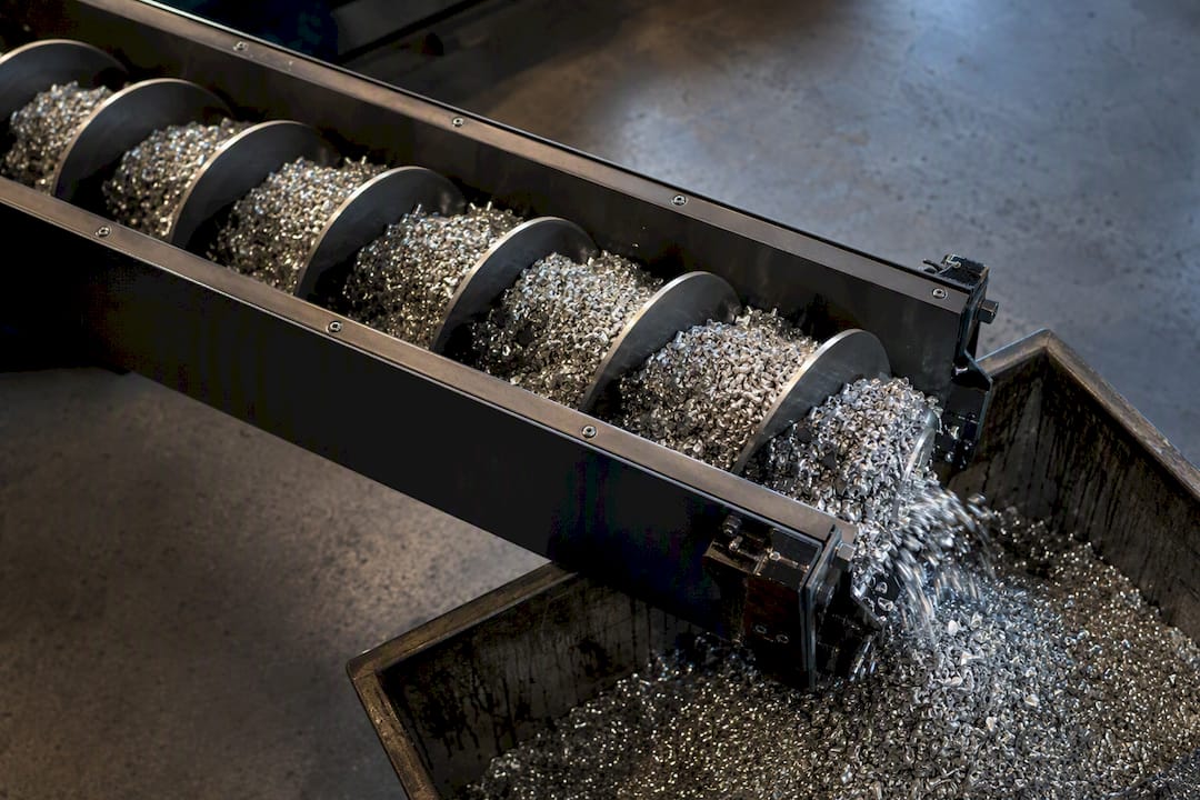
Extraction nuts and centrifugal extraction earn their keep on routing and nesting operations where loose, light aluminium swarf floats rather than falling cleanly onto a conveyor bed.
Key specification points for procurement:
- Conveyor throughput of at least 0.5 metres per second to prevent accumulation during continuous cuts.
- A dust and chip extraction system matched to enclosure airflow, not bolted on as an afterthought.
| System component | Minimum guidance |
|---|---|
| Through spindle coolant pressure | ≥15 bar at spindle nose |
| Conveyor throughput | ≥0.5 m/s |
| Conveyor sizing margin | ~2× peak calculated chip volume |
Integrated filtration, described in recent research on chip removal and coolant recovery systems, reduces recirculation of fine chip debris and cuts coolant waste at the same time.
Reading the warning signs before a tool breaks
Flute packing rarely happens without warning. A rising pitch in spindle sound, a torque spike on the controller, or a sudden change in chip colour leaving the cut are the three signals worth training operators to notice, and pairing that with controller based tool life monitoring catches drift before it becomes a snapped tool.
When you see it happening mid-cut:
- Back off the plunge rate immediately.
- Redirect the nearest air or coolant nozzle straight at the flute exit.
- If packing persists, pull the tool and inspect for BUE before continuing.
Longer term, a repeat packing problem usually points to a CAM strategy or tool geometry mismatch, not a one-off fluke. Swap in trochoidal passes, revisit helix angle, or reconsider whether the machine’s coolant pressure was ever adequate for the job.
Pro Tip: Log every packing event with the tool, material thickness and program name attached. Patterns show up after three or four incidents that a single bad cut never reveals.
What system upgrades actually fix at production scale
Isolated fixes, a new nozzle here, a faster feed there, rarely solve chip problems that show up across an entire production run. The pattern Anderson sees across metalworking customers is that incidents cluster around underspecified coolant pumps and conveyors sized for a lighter material than aluminium actually produces. Trade analysis on aluminium machining efficiency backs this up, tying systemic fixes, coolant mapping, tool alignment and conveyor capacity, to measurable drops in rework and unplanned tool changes.
Before specifying or upgrading a machine, an engineer should confirm:
- Pump pressure rated for through spindle coolant at 15 bar or higher.
- Spindle coolant port sized for the tool diameters actually run in production.
- Conveyor rating matched to peak chip volume, not average.
- Extraction options suited to the mix of slotting, routing and drilling on the floor.
A shop engineer’s take on chasing chip control
Run a representative test coupon before touching the production program. Photograph flute condition after the cut and log how much material packed into the gullet. Chip control and throughput pull against each other constantly, and it’s tempting to just push feed rate until something breaks. Small, tracked trials beat guesswork every time, and a simple operator checklist catches problems long before a tool snaps.
— Scott
How Anderson helps you fix chip evacuation at the machine level
A cutter swap only gets you so far when the machine underneath it can’t keep pace. Some manufacturers build metalwork machining centres with through spindle coolant delivery, pump pressure suited to continuous aluminium slotting, and integrated extraction designed around real chip volume, not a spec sheet minimum.

For shops running aluminium in high mix production, the Production Machining Centre with APC pairs automated pallet changing with the coolant capacity heavier slotting demands, while the Vertical Machining Centre range gives engineers configurable coolant port and pump options to match the procurement checklist above. If you are speccing a new cell around aluminium volume rather than steel, Anderson’s metalwork CNC machinery range is worth a direct look. Get in touch for a specification review before you commit to a machine that was never built for the chip load you’re actually producing.
Where to go deeper on chip evacuation
For the technical detail behind the recommendations above, HMN Tool’s aluminium chip evacuation guide covers flute and coating selection in depth, while Cutwel’s aluminium machining guide explains coating chemistry. For system level specification, the aluminium machining efficiency analysis ties coolant, conveyor and toolpath decisions together.
Sources
- Integrated chip removal and coolant recovery system for CNC machine tools (2026 DOI)
- Aluminum end mill chip evacuation guide | HMN Tool
- Efficient machining process for aluminium alloys — Why chip evacuation defines success