

Set tolerances from part function, mating requirements, material and verified process capability. State the applicable drawing standard and general tolerances explicitly; do not assume that every shop or feature uses the same default value.
TL;DR:
Specify tolerances on the drawing according to function and verified manufacturing capability; avoid treating one default tolerance as universal.
Tolerance notation styles include bilateral, unilateral, and limit dimensions, and using a general tolerance note reduces the need for detailed dimensioning on every feature.
Achievable tolerances depend on the operation, with single-setup machining and multi-face finishing reducing stack-up errors, while grinding or lapping may be necessary for very tight controls.
GD&T offers more precise control for geometry and fit, especially for features like hole patterns and flatness, and its correct use can reduce size tolerances and costs.
Tighter tolerances often require secondary processes and increase lead time and expense, so engineers should justify any tight callouts with functional reasons and verify inspection methods early.
Table of Contents
What is a CNC tolerances guide meant to teach you?
A tolerance defines the permitted variation around a nominal dimension. State it unambiguously and agree the drawing conventions and inspection method with the manufacturer.
Three notation styles show up constantly:
-
Bilateral (±): “25 ±0.05 mm” allows deviation in both directions equally.
-
Unilateral: “25 +0.10/−0.00 mm” allows growth only, common on shafts that get ground down later.
-
Limit dimensioning: “24.95–25.05 mm” states both bounds directly, no plus-minus math required.
Use an explicit general tolerance note where appropriate, selected for the drawing and part requirements. Apply individual tolerances when function demands them.
How tight should CNC tolerances be by default?
ISO 2768 sets four tolerance classes for linear and angular dimensions: fine (f), medium (m), coarse ©, and very coarse (v). Most general engineering drawings reference class m or f, and calling out “general tolerances per ISO 2768-m” in the title block is enough to cover every non-critical dimension on the part.
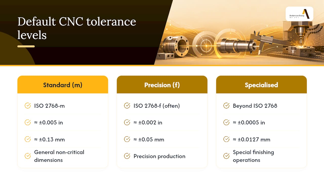
Published examples of machining tolerances describe particular processes and conditions. Confirm what the intended process can achieve on the actual material, geometry and size.
Reach for ISO 286 instead of ISO 2768 the moment you’re specifying a fit between two mating parts, a shaft and a bearing bore, for example, because ISO 286 defines the hole and shaft tolerance grades (H7, h6, and so on) that actually govern clearance and interference. Reach for GD&T under ASME Y14.5 or ISO 1101 when the requirement is really about geometry, flatness, position, perpendicularity, rather than raw size.
Which tolerances are achievable by machine and operation?
Tolerance capability tracks the operation that finishes a feature, not just the machine badge on the spindle. A hole that’s drilled and left as-is behaves very differently from the same hole reamed to size.
Single-setup machining matters more than most drawings acknowledge. Every time a part comes off the machine and gets re-fixtured, positional tolerances stack up across that new datum reference. A 5-axis vertical machining centre that completes five faces in one clamping removes several of those stack-up sources entirely, which is often the real reason a “harder” tolerance turns out cheaper on a multi-face part than the equivalent job run across three separate ops on a 3-axis mill. When a spec genuinely needs sub-0.01 mm control, plan for grinding or lapping as a secondary operation rather than asking a milling cutter to hold it directly.
When does GD&T beat a simple linear tolerance?
Linear tolerances control size. They say nothing about whether a hole pattern lines up with the mating part, or whether a sealing face is actually flat. That’s where GD&T under ASME Y14.5 earns its keep, and it splits into five practical categories:
-
Form (flatness, straightness, circularity): controls the shape of a single feature independent of any datum.
-
Orientation (perpendicularity, parallelism, angularity): controls how a feature sits relative to a datum.
-
Location (position, concentricity): controls where a feature sits, most commonly used for hole patterns.
-
Profile: controls a complex surface or edge against a theoretical shape.
-
Runout: controls surface variation on rotating parts.
A bolt-hole pattern is the classic case for true position rather than ± coordinate tolerancing, because position tolerancing defines a circular tolerance zone instead of a square one, giving genuinely more usable area for the same nominal spec. A pump housing face needs flatness, not just a thickness tolerance, because a face that’s in tolerance for size can still leak if it’s bowed. A mounting boss usually needs perpendicularity to the base, not a tighter diameter tolerance.
Datums matter as much as the control itself: define them in a logical order (primary, secondary, tertiary) that matches how the part actually sits in its assembly or fixture. MMC and LMC qualifiers (maximum and least material condition) let you trade extra position tolerance for reduced size tolerance, which is one of the most underused cost levers on a drawing.
Pro Tip: Before you tighten a size tolerance to fix an assembly problem, ask whether a geometric control would fix it instead. GD&T often lets the machinist work within a wider size range while still guaranteeing the fit, which usually costs less to produce.
How do you calculate the right tolerance for a fit?
Setting a tolerance isn’t guesswork if you work through it in order.
-
Identify the functional requirement. A shaft going into a bearing bore needs a defined fit, clearance, transition, or interference, not just “make it round.”
-
Select the fit class. For a running clearance fit, H7/h6 is the standard reference from ISO 286: the hole (H7) and shaft (h6) tolerance grades that together deliver a predictable, small clearance.
-
Check the specified fit or tolerance against the relevant standard and nominal size. Do not convert a one-sided tolerance zone into a symmetric plus/minus callout without preserving its limits.
-
Calculate the stack-up across every mating interface in the assembly, not just the single dimension you’re worried about.
Worked example: a 20 mm shaft toleranced to h6 runs from 19.987 mm to 20.000 mm. The mating bore at H7 runs from 20.000 mm to 20.021 mm. That gives a guaranteed clearance between 0.000 mm and 0.034 mm, tight enough for a sliding fit, loose enough that a reamed bore and a ground shaft can both hold it in normal production.
What limits an achievable CNC tolerance in practice?
A drawing tolerance is only as real as the process that can hit it, and four variables decide that more than anything else:
-
Material behaviour: aluminium expands roughly twice as fast as steel per degree of temperature change, so a part machined warm and measured cold can drift outside a tight tolerance without anyone touching it.
-
Feature geometry: thin walls flex under cutting force, deep pockets trap heat and chips, and long unsupported bores let the tool deflect away from centre.
-
Fixturing and toolpath: a poorly clamped part moves mid-cut, and an aggressive toolpath strategy on an unstable machine will chatter before it holds a tight number.
-
Measurement method: a caliper reads to roughly 0.02 mm confidence, a micrometer tighter again, but true position and flatness callouts genuinely need CMM probing or a bore gauge to verify with any certainty.
Does surface finish change the final dimension?
Yes, and it’s one of the most common places a drawing gets ambiguous. Typical Ra bands run from 3.2 µm for a standard as-machined surface down to 0.4 µm or finer for ground or polished work, and each step down adds cost.
-
Plating typically adds 0.005–0.05 mm per surface, depending on the process and coating thickness.
-
Anodising adds a thinner layer but still shifts critical bore and thread dimensions measurably.
-
Heat treat can warp thin or asymmetric parts enough to require final machining afterward.
State plainly on the drawing whether a tolerance applies before or after finishing, and call out final inspection post-finish on any feature where plating or heat treat could push it out of spec.
Is a tighter tolerance always worth the extra cost?
Rarely, and this is where a lot of drawings quietly bleed money. Every step tighter than block tolerance adds slower feeds, more in-process inspection, and higher scrap risk, and design guides consistently warn against blanket-tight specs for exactly that reason.
-
Tolerances beyond standard shop capability often push jobs toward secondary operations: grinding, lapping, or EDM.
-
Each of those adds a separate setup, its own fixturing, and its own inspection step.
-
Review every feature for its functional need and inspection requirement; do not allocate tight tolerances using a fixed percentage of features.
A tighter tolerance may require different tooling, processing or inspection. Confirm the effect through a process plan rather than assuming a fixed cycle-time relationship.
What should a well-specified drawing include?
A drawing that gets machined right the first time follows a short, repeatable checklist.
-
State the general tolerance up front. A line reading “general tolerances per ISO 2768-m unless otherwise specified” sets the baseline for every undimensioned feature.
-
Reserve GD&T callouts for function-critical geometry only. Hole patterns, sealing faces, and mounting interfaces get true position, flatness, or perpendicularity; everything else stays on the general note.
-
Specify inspection method, sample size, and acceptance criteria for any tight callout, so the shop knows whether a caliper is acceptable or a CMM report is required.
-
Flag pre or post-finish tolerances explicitly wherever plating, anodising, or heat treat is in the process chain.
Pro Tip: Send the drawing to the machinist before it’s finalised, not after. A five-minute DFM conversation catches tolerance mismatches that a design review alone almost never does.
Author perspective: the pragmatic rule for tolerancing
Specify tolerances from the functional requirement and applicable drawing conventions. Select a general-tolerance class deliberately, and use the appropriate geometric controls where needed rather than applying one class to every part.
Before you sign off on a drawing: confirm the inspection method can actually verify what you’ve specified, confirm the machine and operation match the achievable ranges above, and confirm every tight callout traces back to a real functional reason. If you can’t answer why a tolerance is tight, it probably shouldn’t be.
Sources
-
CNC machining tolerances, standards, charts & benchmarks — SolidCAM
-
Understanding CNC machining tolerances — Protolabs design tips
Manufacturers looking to hold tighter tolerances with fewer setups can review Anderson’s 5-axis machining platforms, built to reduce the stack-up that comes from repositioning parts between operations.