
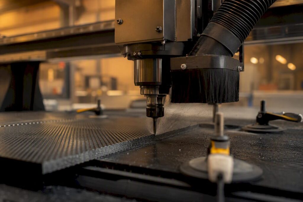
Yes. Carbon fibre machining works reliably once you match the tool to the material, tame your feeds and speeds, and get dust extraction right from the first cut. The material punishes shortcuts, but it doesn’t punish precision.
Before you touch a spindle, run through this:
-
Tooling: PCD or diamond-coated carbide only for anything beyond a one-off prototype.
-
Dust control: extraction rated for fine conductive particulate, not a shop-vac from the hardware aisle.
-
Fixturing: rigid support under every cut line, no unsupported overhang.
Compare waterjet and CNC machining against the composite grade, fibre layup, geometry, tolerances and edge requirements. Validate each proposed process and its contaminant controls rather than selecting from a universal tolerance band.
Key Takeaways
Carbon fibre machining succeeds when tool selection, parameter control, and dust extraction are treated as one integrated system rather than three separate decisions.
| Point | Details |
|---|---|
| Match process to tolerance | Use waterjet for approximately ±0.10 mm tolerance profiles, CNC for between ±0.020 and ±0.050 mm holes and features. |
| Choose tooling by volume | PCD suits production runs; carbide is fine only for one-off or low-volume jobs. |
| Control heat and thrust | Shallow multiple passes and ramp entry beat deep single plunges every time. |
| Extraction is non-negotiable | Conductive, respirable dust demands HEPA filtration and proper PPE, not a shop-vac. |
| Scale up with the right machine | Anderson’s enclosed and 5-axis platforms suit shops moving from prototypes to production volume. |
Table of Contents
-
What spindle speeds and feeds work for cutting carbon fibre sheets?
-
What finishing and inspection checks confirm the part is ready?
-
When does it make sense to invest in your own CFRP machining setup?
Which cutting process suits carbon fibre machining best?
The right process depends on tolerance, part geometry, and how much delamination risk you can tolerate, not on which machine happens to be free that day.
Waterjet cutting produces no heat affected zone and minimal delamination risk, which makes it the safer default for flat panels, external profiles, and roughing large sheets down to near-final size. Its trade-off is tolerance: expect around approximately ±0.10 mm tolerance, which rules it out for mating holes or tight fits. It also can’t cut internal pockets or 3D contours.
CNC milling and routing can provide holes, pockets and three-dimensional features where suitable tooling and access are available. Verify achievable tolerances on the actual composite and setup.
Laser cutting is worth naming only to rule it out for structural work. The resin matrix scorches and delaminates under laser heat, so reserve it for thin, non-structural, decorative pieces where a burnt edge won’t matter.
The workflow that tends to win on cost and cycle time combines the two: waterjet the outer profile to near-final dimension, then bring the part to a CNC centre for precision holes and finishing features. You cut CNC spindle time dramatically because the machine only touches the features that actually need tight tolerance, and tool wear drops because you’re not asking a mill to hog through metres of sheet edge.
-
Flat panel, loose tolerance profile: waterjet alone.
-
Structural bracket with fastener holes: waterjet profile, CNC for holes.
-
Complex 3D contour or mould tool: CNC only, likely 5-axis.
What cutters actually hold up against carbon fibre?
Tool choice is where most carbon fibre CNC machining budgets go sideways, and the fix is choosing by volume, not by what’s in the drawer.
PCD (polycrystalline diamond) tooling is the production standard once you’re running enough parts to justify the upfront cost. PCD inserts deliver significantly longer tool life than carbide in CFRP, and because tool wear directly drives edge quality and dimensional drift, that longevity translates into fewer scrapped parts, not just fewer tool changes. The economic case isn’t really about tool cost at all; it’s cost per part, and PCD usually wins that comparison once you’re above a modest production threshold.
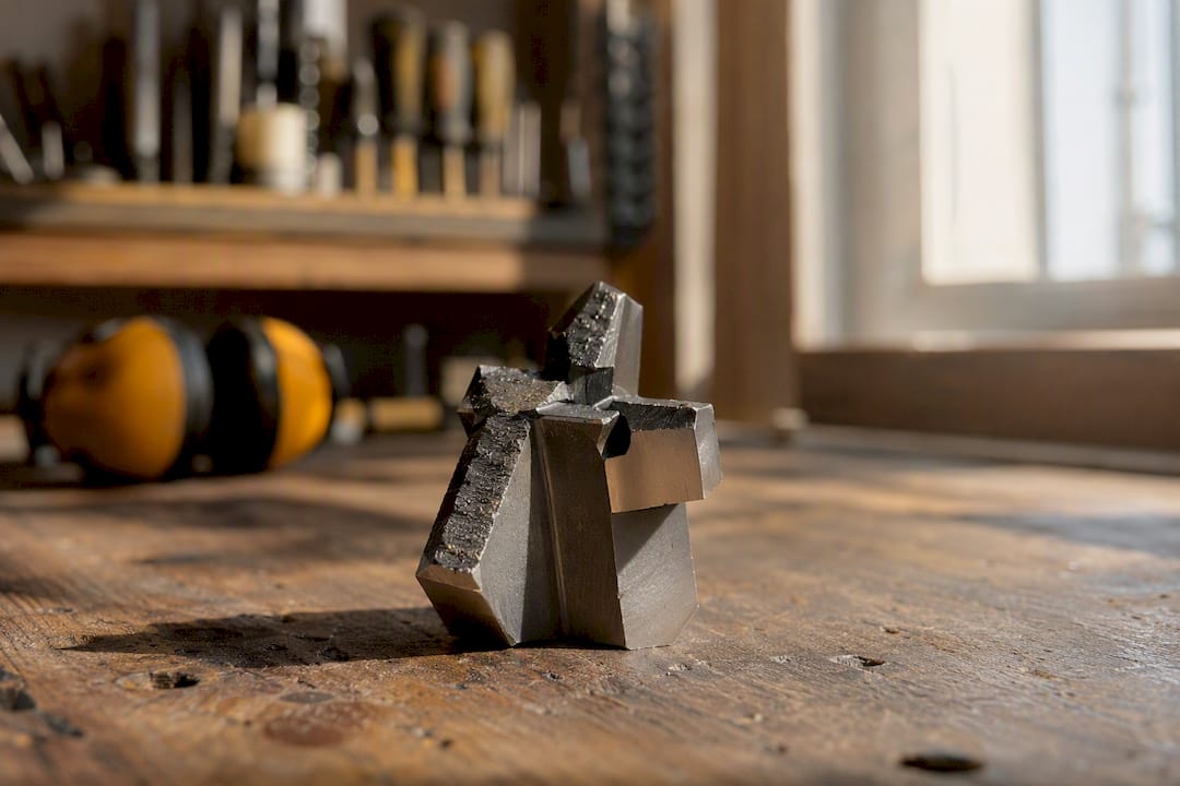
CVD diamond-coated carbide sits in the middle. It handles prototyping and mid-volume runs well and costs less upfront than solid PCD, but the coating is thin, and once it wears through you’re back to bare carbide performance. Re-sharpening diamond-coated tools is possible but often uneconomical, so treat them as consumables rather than an investment.
Plain carbide is fine for a one-off part or a hobbyist project, but expect wear fast. Carbon fibre is abrasive enough that a carbide end mill can lose its edge within a single sheet on some layups, so plan for frequent tool changes and don’t trust dimensional consistency across a long run.
For geometry, compression cutters (up cut on the bottom flute, down cut on top) are worth knowing by name because they solve a specific problem: clean surfaces on both the top and bottom of the panel in a single pass, which single-direction cutters can’t do without tear-out on one face.
Pro Tip: Keep a spare compression cutter on hand for every job over four hours of spindle time. Swapping at the first sign of fibre pullout costs you five minutes; running a worn tool through a $500 layup costs you the whole part.
What spindle speeds and feeds work for cutting carbon fibre sheets?
Carbon fibre doesn’t cut like aluminium or wood, and using metal-cutting instincts on it is the fastest way to blow an edge.
Production practice generally sits in a narrow band: spindle speeds of high spindle speeds in the range of about 18,000 to 30,000 RPM paired with feed per tooth around low feed per tooth in the range of about 0.02 to 0.08 mm. Router setups running lighter finishing passes often land closer to spindle speeds around 18,000 to 25,000 RPM combined with feed rates roughly between 1,000 and 1,500 mm/min, which is a reasonable starting point if you’re dialling in a new setup rather than copying a spec sheet blind.
| Parameter | Typical range | Why it matters |
|---|---|---|
| Spindle speed | 18,000–30,000 RPM | Keeps cutting action clean without excess heat buildup |
| Feed per tooth | 0.02–0.08 mm | Too high tears fibres; too low burns resin |
| Depth of cut | Shallow, multiple passes | Reduces delamination and extends tool life |
| Finishing pass | Light, final pass | Removes fuzz and stabilises dimension |
Depth of cut is where patience pays off. Shallow, repeated passes beat one aggressive plunge every time, because multiple light passes preserve edge quality and tool life far better than a single deep cut that stresses the laminate all at once.
-
Select entry moves from the toolmaker’s guidance for the composite and operation; avoid a universal rule for every tool.
-
Conventional milling (not climb) often gives better finish control on composites, the reverse of what most metal machinists assume.
-
Reserve your lightest, slowest pass for the final skin cut, treating it as a finishing operation rather than a roughing step.
How do you drill carbon fibre without delamination?
Drilling is where carbon fibre punishes rushed technique hardest, because exit-side delamination and undersize holes both happen in the same half-second of bad practice.
-
Use step drills or dedicated reamers rather than standard twist drills. Staged geometry reduces thrust force as the tool progresses, which is the main cause of exit-face push-out.
-
Peck cyclically at low feed rates instead of drilling through in one motion. Short pecks clear chips and let heat dissipate before it softens the resin around the hole wall.
-
Back every exit face with a sacrificial plate. Support on the exit side is one of the most effective single changes you can make to stop the classic drilling failure: fibres punching out the back as the drill breaks through.
-
Account for lamina relaxation. CFRP holes can shift dimensionally after drilling as internal stress redistributes, so measure finished holes against spec rather than trusting the programmed diameter, and build compensation into your CAM file where the tolerance is tight.
Pro Tip: If your parts need holes tighter than ±0.02 mm on a critical fastener pattern, it’s often cheaper to subcontract that operation to a specialist than to chase relaxation error on your own machine for weeks.
What workholding actually keeps carbon fibre panels stable?
Movement during a cut is the quiet killer of carbon fibre parts. Even a fraction of a millimetre of flex near the cutter edge shows up as fuzz, chipping, or a dimension out of spec.
Vacuum tables work well for thin, flat panels because they hold the whole surface down evenly without point-loading the laminate. Their limitation shows up on parts with cutouts or complex profiles, where lost vacuum seal around internal features leaves sections unsupported exactly where you need rigidity most.
Sacrificial backing plates solve the exit-side support problem for both routing and drilling. Specify the plate in a material soft enough to sacrifice (MDF or dense foam works for most shops) and thick enough that it doesn’t flex under clamp pressure, generally matching or exceeding the panel’s own thickness.
-
Vacuum tables: best for flat sheet stock, weak on cutout-heavy geometry.
-
Backing plates: essential under every drilled or routed exit face.
-
Mechanical clamps: position them well clear of critical features. Clamping pressure near a hole pattern or edge you’re about to cut can distort the laminate just enough to throw off your tolerance.
How much dust extraction does carbon fibre machining need?
Carbon fibre dust isn’t just a nuisance to sweep up. Monash University’s health and safety guidance flags it as a genuine respiratory hazard that is also electrically conductive, meaning it poses a risk to both the people in your shop and the electronics inside your machine.
That conductivity risk is easy to underestimate until fine particulate works its way into a control cabinet and starts causing intermittent faults or shorts. Extraction isn’t optional gear here; it’s part of protecting the capital equipment as much as the operator.
-
Dry extraction (vacuum) suits most shops: fine filtration captures airborne particulate before it settles on rails, sensors, and electrical components.
-
Wet machining suppresses dust almost entirely at the cutting point but creates a slurry that needs proper containment and disposal, and it complicates any downstream bonding or coating step that needs a dry, clean surface.
-
Specify extraction, filtration and protection of machine components for the actual composite and dust hazards. A HEPA label or sealed enclosure alone does not establish that the complete system is suitable.
-
PPE minimums: P2/N95-rated respirators at minimum, safety glasses, and long sleeves to avoid skin irritation from fine fibre fragments.
What finishing and inspection checks confirm the part is ready?
A part isn’t finished the moment the last toolpath ends. Finishing and inspection are where you catch the defects that cutting alone won’t reveal.
-
Run a final light finishing pass at a lighter feed than your roughing passes to clear fuzz and stabilise the true edge dimension.
-
Progress through sanding grits rather than jumping straight to fine paper. Coarse first to remove fibre whiskers, then progressively finer to prep for bonding or coating.
-
Clean with isopropyl alcohol before any adhesive or paint step. Skipping this is a common reason bonded joints fail later.
-
Inspect against real limits, not guesswork: check hole tolerance against spec, look for delamination depth at cut edges, and verify surface finish (Ra) meets the drawing requirement.
-
Seal exposed edges where the part will see moisture or repeated handling. Edge sealing isn’t always necessary, but skip it on any part exposed to weather or fuel and you’re inviting wicking.
How do you manage tool wear before it ruins a batch?
Tool wear in carbon fibre machining doesn’t announce itself the way it does in metal. There’s rarely a dramatic tool failure, just a slow creep in edge quality that can ruin an entire batch before anyone notices the cutter is past its prime.
Set tool-change intervals based on actual run history for that specific tool and part geometry, not a generic manufacturer number pulled from a metal-cutting catalogue. A PCD tool cutting simple straight profiles will outlast one working complex 3D contours on the same material.
Machine features matter more here than in most other materials:
-
Tool-life management systems that track cutting time per insert and flag changes automatically.
-
Rigid spindles that resist deflection under the higher cutting forces composites can generate at certain feed rates.
-
Enclosed work areas that make dust extraction genuinely effective rather than aspirational.
-
Auto pallet changers where volume justifies minimising downtime between parts.
Machines built with tool-life management, robust extraction, and rigid construction meaningfully reduce scrap risk when you’re running composites at any real scale. Anderson’s AXXIOM 5-axis series and enclosed MASS-B platform are built around exactly this combination for shops moving from prototype runs into production volume.
Composite machining rewards shops that treat tool wear as a scheduled maintenance item, not a surprise. The cost of a missed tool change is never just the tool. It’s the part, the material, and the time already sunk into getting that far.
When does it make sense to invest in your own CFRP machining setup?
The honest answer depends on volume and how much quality risk you can absorb from a subcontractor’s queue. If you’re running fewer than a few hundred parts a year, PCD tooling and a dedicated dust-controlled cell rarely pay for themselves against a specialist’s per-part rate.
Above that threshold, the maths flips. PCD tool life and consistent parameters start beating subcontract pricing, especially once you factor in lead time and the quality risk of handing critical parts to someone else’s process. Full 5-axis capability is justified once your parts move past flat panels into genuine 3D contours, where sturz milling techniques and multi-axis access aren’t a luxury, they’re the only way to hit the geometry at all.
I’d rather see a shop outsource one complex batch and learn from the supplier’s process notes than buy a machine it can’t yet keep fed with volume.
Get set up for carbon fibre machining the right way
Anderson is the option for manufacturers who’ve outgrown subcontract queues and need composite capability built into the machine itself, not bolted on after the fact. Where a generic router forces you to compromise on extraction or rigidity, Anderson’s platforms are specified with enclosed work zones, rigid spindles, and tool-life tracking as standard, so you’re not fighting the machine while you’re still learning the material.

If your parts are moving past flat panels into 3D contours or fastener-critical assemblies, the AXXIOM 5-axis series gives you the axis access sturz milling needs, while the enclosed MASS-B suits shops prioritising dust containment on production runs. Anderson also supports aerospace, automotive, and marine manufacturers working across advanced materials well beyond composites alone. Get in touch to talk through your part geometry and volume, and find out which platform actually fits your production line.
Frequently asked questions about carbon fibre machining
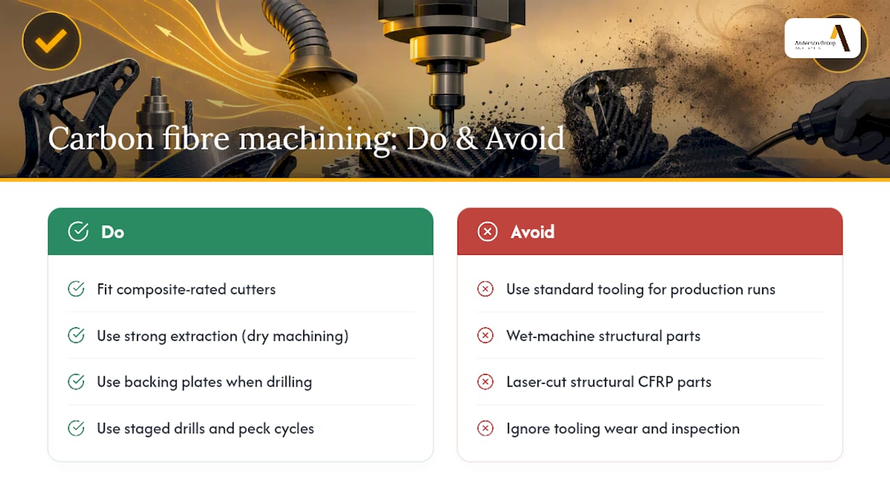
Can standard CNC routers cut carbon fibre? A standard router can cut carbon fibre for light, occasional work if fitted with a composite-rated cutter and proper extraction, but repeated production runs will wear out non-specialist tooling fast and risk inconsistent edge quality.
Dry or wet composite machining must be selected for the material, process, equipment and downstream requirements. Assess emissions and any slurry handling; do not assume one method is suitable for all carbon-fibre work.
Why does carbon fibre delaminate during drilling? Delamination on the exit side usually comes from unsupported backing and excessive thrust force. Backing plates, staged drills, and peck cycles address the three biggest contributors.
Is laser cutting ever suitable for carbon fibre parts? Only for thin, non-structural, decorative pieces. Structural CFRP parts should avoid laser cutting because resin heating at the cut edge weakens the laminate.
How much more does carbon fibre machining cost than aluminium? Expect roughly 2 to 5 times higher machining cost than comparable aluminium parts, driven by tooling wear, slower feeds, and the extra overhead of extraction and inspection.
Sources
-
Carbon fibre composites OH&S information sheet — Monash University HSW
-
Carbon fiber CNC machining: process, tools, cost & design — Rapid Protos
-
Machining carbon fiber: process selection, cost & quality guide — CNCMachiningShops