
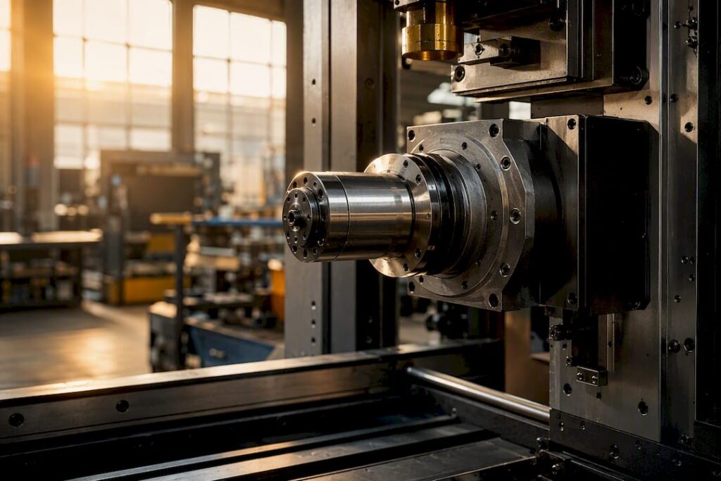
For continuous, high-precision production, robust motorised electrospindles and heavy-duty direct-drive units outperform lighter air-cooled options every time, provided you match the torque curve to your actual duty cycle. The single most important factor isn’t kilowatts or maximum RPM. It’s whether the spindle can sustain its rated torque continuously (an S1 rating) without thermal growth throwing your tolerances out over an eight-hour shift.
Before you request a single quote, pull together three things:
-
Your typical cutting loads across the materials you actually run, not the easiest job in the shop
-
The controller and mechanical specs of the machining centre the spindle needs to sit inside
-
A realistic picture of your duty cycle: is this spindle running flat out for ten minutes an hour, or ten hours straight?
Spindles rated for permanent-magnet synchronous motor designs now dominate the mid-to-high-end of the market because they hold speed regulation and precision better than older induction designs, according to a 2025 review of electric spindle motor technologies. That’s the baseline worth knowing before you compare anything else.
Key Takeaways
Matching a spindle’s continuous torque rating and thermal growth behaviour to your actual duty cycle predicts production performance far better than comparing peak kW or maximum RPM.
| Point | Details |
|---|---|
| Prioritise the torque curve | Match continuous S1 torque, not peak kW or RPM, to your actual cutting loads and duty cycle. |
| Cooling depends on cycle length | Liquid cooling stabilises thermal growth for sustained production; air cooling suits light, intermittent work only. |
| Taper choice affects rigidity | HSK suits high-speed dual-contact clamping; ISO/BT remain solid for heavier, lower-speed cutting. |
| Verify control compatibility first | Confirm VFD protocol, voltage, phase, and encoder needs before accepting any spindle spec. |
| Anderson supports the full process | Anderson Group Australia specifies, integrates, and maintains production spindle packages across its 5-axis and vertical machining centre ranges. |
Table of Contents
-
Discussing production spindle requirements with Anderson Australia
-
Spindle precision and runout: the numbers that actually matter
-
Noise, vibration, and what they tell you about machining quality
-
How Anderson helps you specify and install the right spindle
Understanding your CNC spindle options for production work
Three spindle families cover almost every production scenario, and picking the wrong one is the most expensive mistake you can make before the machine even arrives.
Motorised electrospindles integrate the motor directly into the spindle housing, eliminating belts and the mechanical losses that come with them. They spin fast, run quiet relative to geared alternatives, and deliver the fine speed control that finishing operations demand. The trade-off is heat: because the motor sits inside the spindle cartridge, thermal management becomes non-negotiable rather than optional. Machining centre spindles across the market commonly span 0 to 40,000 RPM, with dynamic stability varying sharply between designs at either end of that range.
Direct-drive and heavy high-torque spindles sacrifice top-end speed for grunt at low RPM. If you’re hogging aluminium billet, machining titanium forgings, or running deep pockets in tool steel, you need torque that holds up at 2,000 to 6,000 RPM, not a spindle that only gets impressive above 15,000. These units suit aerospace structural parts and heavy automotive tooling far better than a high-speed finishing spindle ever will.
Belt and gear-driven systems remain relevant where serviceability and torque multiplication matter more than ultimate speed. They’re easier to rebuild in-house, cheaper to maintain long-term, and can multiply torque mechanically rather than relying purely on motor design.
A growing number of shops are moving toward modular spindle systems with wide torque-speed ranges that can be tuned to the job, which lifts first-pass yield across mixed production runs rather than locking the machine into one narrow application. Whether you retrofit an existing machining centre or specify a spindle as part of a new build matters here too. Factory-integrated units are engineered as a system with the machine’s structure and control, while retrofits demand careful checking of stack height, mounting, and control compatibility.
Cooling and thermal management for continuous runs
Heat is the enemy of repeatability, and cooling strategy is where most spindle failures in continuous production actually start.
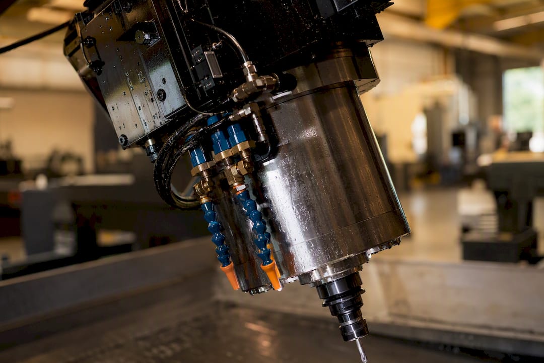
Air-cooled spindles work fine for intermittent or light-duty applications, but their thermal stability is limited on long, sustained cycles. Liquid or water-cooled systems stabilise thermal growth more effectively across full shifts, which is why most serious production shops typically prefer them despite the need for chillers and regular maintenance, according to a buying guide focused on matching spindle cooling to actual shop processes. Oil-mist systems sit in between: less thermal stability than full liquid cooling, but simpler plumbing and lower running costs.
| Cooling type | Best suited to | Key maintenance demand |
|---|---|---|
| Air-cooled | Intermittent, light-duty cycles | Minimal, but limited thermal headroom |
| Oil-mist | Moderate-duty, mixed production | Mist system upkeep, filter checks |
| Liquid/water-cooled | Continuous, high-precision production | Chiller sizing, coolant quality, scheduled servicing |
Thermal growth needs to be specified and tested, not assumed from RPM or kW figures on a spec sheet. Two spindles with identical headline numbers can behave completely differently once they’ve been running for four hours.
Pro Tip: Ask any vendor for thermal growth data measured under a load profile that matches your actual work, not their marketing benchmark. A spindle tested at a light load for fifteen minutes tells you almost nothing about what happens on your floor at hour six.
Reading torque curves and choosing the right taper
A torque-speed curve tells you more about real-world performance than any single spec on a data sheet, and most buyers still skip past it.
Every spindle has a curve that shows constant torque up to a base speed, then a constant-power region where torque falls as RPM climbs. If your work sits mostly below that base speed, that’s the number that matters, not the spindle’s maximum RPM rating. Heavy stock removal in steel or titanium lives in the low-speed, high-torque zone. Fine finishing in aluminium or composites lives in the high-speed, lower-torque zone. Buying a spindle optimised for the wrong end of its own curve is a common and expensive mistake.
Toolholder taper choice compounds that decision. HSK tapers use dual-contact clamping (face and taper) that suits high-speed, high-precision work and holds rigidity better as RPM climbs. ISO and BT tapers remain common in heavier, lower-speed cutting where taper-only contact is proven and the tooling is often cheaper to stock, based on practical spindle selection guidance from precision spindle specialists.
Drawbar systems matter just as much:
-
Hydraulic drawbars deliver consistent, adjustable clamping force and suit high-throughput shops running frequent tool changes
-
Servo drawbars offer precise, programmable clamping force for demanding multi-material production
-
Simple air drawbars are the cheapest option, but they’re the first thing to underperform once your tool-change count climbs into the hundreds per shift
Permanent-magnet synchronous motors remain the dominant choice for spindles pairing wide speed regulation with strong torque delivery across this range, and variable-flux hybrid designs are emerging as an option for shops needing an even wider useful speed band, though that flexibility brings added cost and control complexity.
How to choose a CNC spindle: a five-step checklist
Specifying a spindle correctly is a process, not a guess. Here’s the sequence that keeps procurement teams from getting burned.
-
Gather your process inputs. Document the materials you cut, typical cutter diameters, target material removal rates, and your realistic duty cycle across a full shift, not your best-case job.
-
Request the real performance data. Ask every vendor for the torque-speed curve, the continuous S1 rating (not just peak output), and thermal growth figures under a representative load. A speed, feed, and MRR calculator is useful here for checking whether the spindle’s torque curve can actually deliver the cutting power your job needs.
-
Confirm control compatibility. Verify the spindle’s control protocol (0 to 10V, Modbus, CANopen), voltage and phase requirements, and any encoder needs against your controller before you sign anything, drawing on integration checklists used across the expert spindle buying guidance.
-
Check the mechanical fit. Confirm stack height and vertical clearance, tool-change compatibility, and required balance class. A spindle that’s mechanically perfect on paper but two centimetres too tall for your column is a wasted quote.
-
Validate service and total cost. Check spare parts availability, local service response times, and build a three-year total cost of ownership estimate that includes coolant, filters, bearings, and expected downtime.
Pro Tip: Run the numbers on total cost of ownership before you compare purchase price. A cheaper spindle with a six-week parts lead time from overseas can cost you more in lost production than a pricier unit with local support.
Discussing production spindle requirements with Anderson Australia
Anderson Group Australia supplies CNC machinery, servicing and spare parts. Confirm the exact machine configuration, installation arrangements and available support with the team.
Several Anderson machine platforms are built to be specified with production-grade spindles suited to continuous work: the Genesis PLUS nesting centre for panel processing, the MASS-B enclosed 5-axis system, the AXXIOM 5-axis series, and the MASS-5 large-scale 5-axis centre for heavier stock.
Thermal growth stability and taper retention at speed are often the real limiters of unattended, long-run production. Demand vendor test data for both under loads that resemble your actual shift rather than a marketing benchmark.
Matching spindle choice to the material you actually cut
Spindle selection can’t happen in isolation from the material sitting on the table, because torque demand, heat generation, and chip evacuation all shift dramatically between substrates.
Aluminium and softer non-ferrous metals reward high-speed spindles with strong constant-power performance, since the metal cuts easily but heat builds fast at high feed rates. Steel, stainless, and titanium demand the opposite profile: high torque at low-to-mid RPM, stiffer bearings, and cooling systems that can handle sustained thermal load without drifting. Composites and advanced plastics bring their own complications, mainly abrasive wear on bearings and the need for reliable dust or particulate extraction integrated with the spindle housing.
Timber and engineered wood panels sit in a different category again. Nesting and cabinetry work generally favours high-speed spindles that prioritise surface finish and clean edge quality over raw torque, since the cutting forces involved are far lower than metal removal. A shop running mixed materials, timber one week and aluminium fixtures the next, needs to think hard about whether one spindle can genuinely serve both jobs well, or whether it’s compromising on both.
Getting this match wrong doesn’t just hurt tool life. It shows up as chatter, poor surface finish, and inconsistent tolerances that trace straight back to a spindle working outside its intended envelope.
Spindle precision and runout: the numbers that actually matter
Runout, the deviation of the tool tip from its true rotational axis, determines your achievable surface finish and tolerance more directly than almost any other spindle spec.
Dynamic runout (measured while the spindle is running, not stationary) is the figure worth demanding from any vendor, because static runout tells you almost nothing about behaviour at operating speed. Precision-grade spindles for finishing work typically need runout held to a few microns at the tool tip, while roughing operations can tolerate more without visibly affecting the result. Bearing quality, spindle balance, and the taper interface all feed into this figure, which is why a well-maintained HSK interface with dual-contact clamping tends to hold tighter runout at speed than a worn ISO taper.
Balance class matters just as much as runout, particularly at higher RPM where even small imbalances generate vibration that compounds over an eight-hour run. A spindle assembly balanced to a tighter grade costs more upfront but pays that back in tool life and surface consistency, especially on finishing passes where the cutter is skimming rather than hogging material. Ask for the balance grade and the RPM at which it was measured. A grade quoted at low speed isn’t the same guarantee at your actual operating RPM.
Noise, vibration, and what they tell you about machining quality
A spindle that’s noticeably louder or rougher than it should be is rarely just an annoyance. It’s usually telling you something about bearing wear, imbalance, or a mismatch between the spindle and the load it’s being asked to carry.
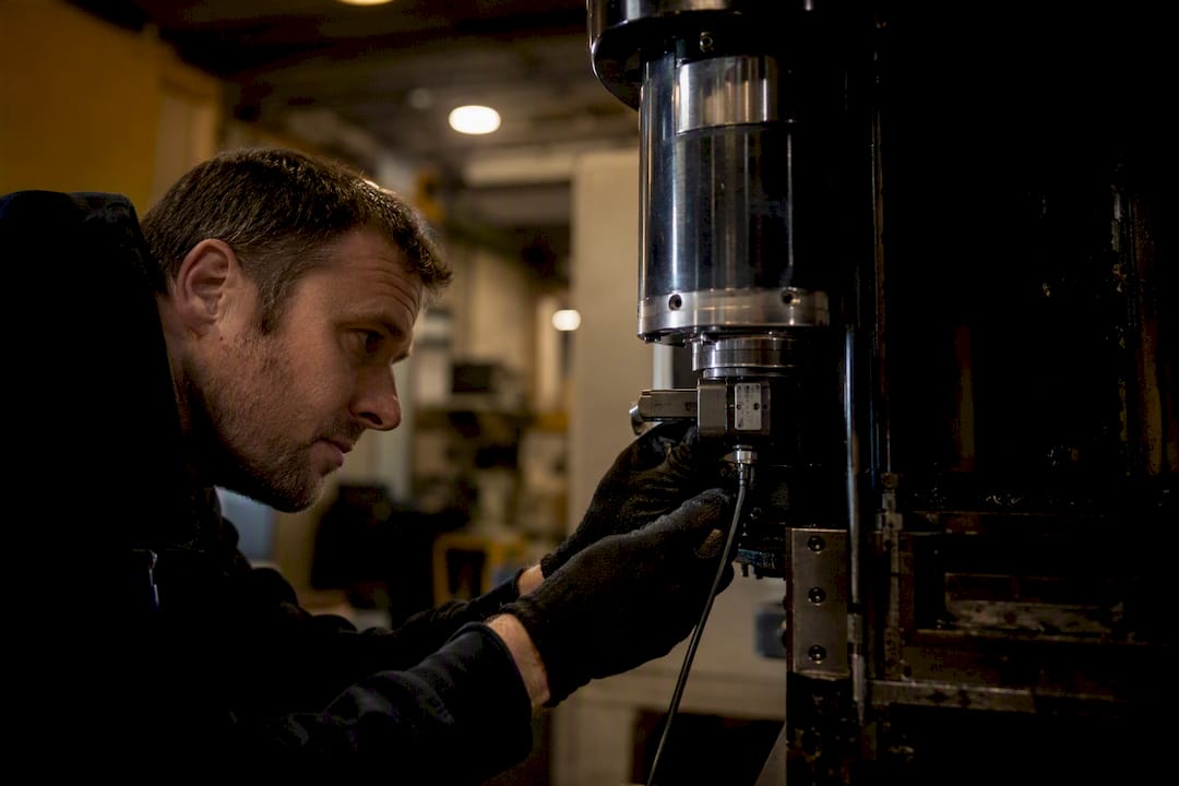
Excessive vibration transmits directly into the workpiece, showing up as chatter marks, inconsistent surface finish, and accelerated tool wear. On finishing operations, even vibration too small to hear clearly can leave a measurable texture on the part, which matters enormously in aerospace and marine work where surface finish specifications are tight. Vibration also fatigues the spindle bearings faster than normal operation, shortening service life and increasing the frequency of costly rebuilds.
Noise level itself isn’t purely a comfort issue either, though it matters for compliance with workplace noise exposure standards in busy production floors. A spindle running noticeably louder than its rated baseline is often flagging a developing mechanical issue well before it becomes a failure. Shops running multiple machines side by side benefit from tracking baseline noise and vibration signatures per spindle, so a shift away from that baseline gets caught in a maintenance check rather than in a batch of scrapped parts.
Integrating spindles with your machine control system
A spindle is only as good as its connection to the controller running it, and this is where otherwise sound purchasing decisions quietly fall apart.
The two dominant control ecosystems, Fanuc and Siemens, and to a lesser extent Heidenhain, each handle spindle orientation, tool change synchronisation, and feedback slightly differently. A Fanuc versus Siemens controls comparison isn’t really about which is “better” in the abstract. It’s about which protocols and communication standards your existing or planned control architecture supports, and whether the spindle you’re specifying speaks that language natively or needs a costly interface layer bolted on. The same applies to Fanuc versus Heidenhain setups, particularly in shops that have grown through acquisition and ended up running mixed control platforms across the floor.
Beyond the controller brand, the VFD (variable frequency drive) driving the spindle needs to match the motor’s control requirements precisely, whether that’s a straightforward 0 to 10V analogue signal or a digital protocol like Modbus or CANopen. Encoder feedback resolution also needs to align with the precision the controller expects for closed-loop speed regulation. Getting this wrong doesn’t just cause an installation headache. It can leave a spindle running in an open-loop mode that never achieves its rated accuracy, no matter how good the hardware is on paper.
Spindle safety features and standards worth knowing
Spindle safety isn’t an afterthought bolted onto the machine. It’s built into how the spindle is engineered, monitored, and integrated with the wider machining centre.
Overload and overtemperature protection, typically monitored through embedded thermal sensors, should shut the spindle down before winding damage occurs rather than after. Overspeed protection prevents the motor from being driven beyond its rated maximum, which matters more than it sounds given how easily a control error or incorrect gear ratio setting can push a spindle past its safe limit. Balance monitoring and vibration sensing, increasingly built into higher-end spindle packages, can flag developing bearing wear before it becomes a safety issue rather than just a quality one.
Tool retention safety matters just as much as the spindle itself. A drawbar system that fails to hold clamping force at speed risks ejecting a tool, which is a genuine safety hazard, not just a scrapped part. This is one of the strongest arguments for hydraulic or servo drawbars over simple air-actuated systems in high-throughput environments, since they maintain consistent, monitored clamping force across thousands of tool change cycles rather than degrading quietly over time. Any production spindle worth specifying should carry documented compliance with relevant machine safety standards for the region it’s operating in, and a vendor unwilling to provide that documentation is worth a hard second look.
Why spec sheets lie and torque curves don’t
The conventional advice on spindle buying is backwards, and it costs shops real money. Most procurement conversations start with kilowatts and maximum RPM because those numbers are easy to compare across a quote sheet. They’re also the least useful numbers for predicting how a spindle behaves on your actual work.
What the research and the mechanics both point to is simpler: a spindle’s continuous S1 rating and its thermal growth under real load tell you almost everything else worth knowing. A spindle can look identical to a competitor on paper and behave completely differently after four hours of continuous cutting, because that’s exactly the condition most spec sheets never test.
If there’s one habit worth adopting, it’s this: stop asking vendors “what’s the top speed?” and start asking “show me the torque curve and the thermal growth data for a load like mine.” Shops that make that switch tend to buy spindles that actually fit the work, rather than spindles that win on a headline number and disappoint by lunchtime on day one of production.
How Anderson helps you specify and install the right spindle
Working through torque curves, cooling requirements, and taper compatibility on your own is doable, but it’s a lot easier with a supplier who configures the whole machine around the spindle, not just the spindle in isolation. Anderson works directly with manufacturers to specify custom spindle integration, match machine configuration to your material mix, and supply the chillers and accessories that keep thermal performance where it needs to be.

That support doesn’t stop at commissioning. Anderson provides ongoing maintenance and technical support once the machine is running production, which matters more than most buyers realise once a spindle is three years into a duty cycle. If your work spans multiple materials, the furniture and cabinetry and metalwork machinery pages outline configurations built for those specific production environments, and the full industries overview covers aerospace, automotive, and marine applications as well. The practical next step is straightforward: get in touch with Anderson to request a technical meeting or site survey, so your torque, cooling, and control requirements get mapped against a real machine configuration before you commit to a quote.
Frequently asked questions
What’s the main difference between air-cooled and water-cooled CNC spindle options? Air-cooled spindles handle intermittent or light-duty work well but lose thermal stability over long runs. Water-cooled spindles hold their thermal growth in check across continuous shifts, which is why most production shops running sustained cycles choose liquid cooling despite the added chiller and maintenance burden.
How do I choose between HSK, ISO, and BT toolholder tapers? HSK suits high-speed work through its dual-contact clamping design, which holds rigidity better as RPM climbs. ISO and BT remain solid choices for heavier, lower-speed cutting where taper-only contact is proven and tooling costs are typically lower.
Does Fanuc versus Siemens controls matter for spindle selection? It matters for integration, not raw spindle performance. Each control platform handles spindle orientation, feedback, and tool change synchronisation differently, so confirming protocol compatibility (0 to 10V, Modbus, CANopen) before purchase avoids expensive interface workarounds later.
What continuous rating should I look for in a production spindle? Look for the S1 continuous duty rating, not the peak power figure. A spindle rated for continuous operation at your typical load will hold torque and thermal stability through a full shift, where a peak-rated spindle may degrade in performance well before the day ends.
How much does dynamic runout affect part quality? Dynamic runout, measured at operating speed rather than at rest, directly affects surface finish and tolerance. Finishing operations generally need runout held to just a few microns, while roughing work tolerates larger figures without materially affecting the outcome.