
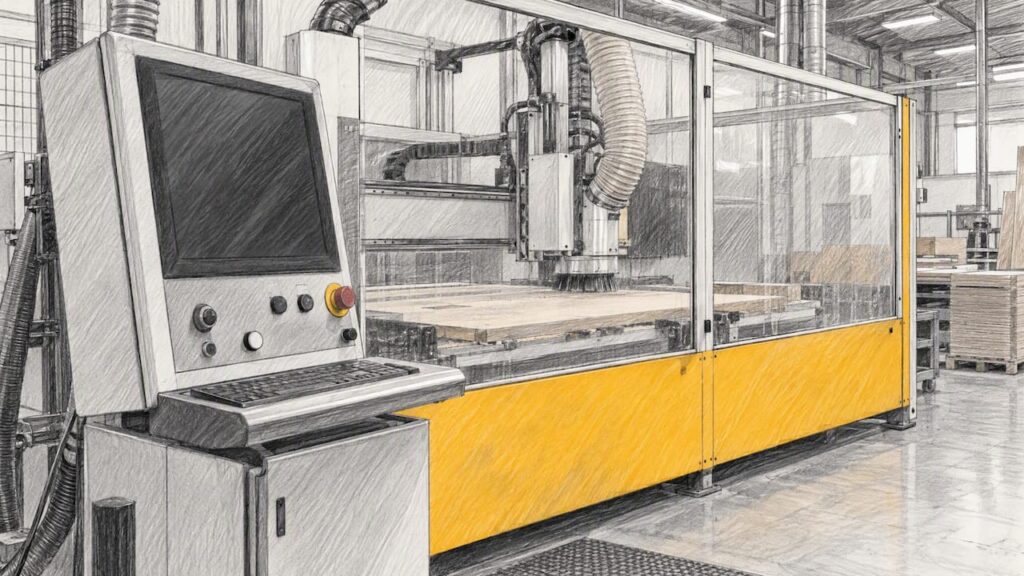
Spindle load monitoring tracks how hard the spindle motor is working, usually as a percentage on the controller screen or in logged data. Used well, it gives an early signal of dull tools, aggressive feeds and a machine drifting from its normal behaviour. Used badly, it produces a number that means different things on different machines. This guide explains what the figure represents, how to read peaks, where the data comes from and how to set baselines. It also covers what to ask before you buy a machine for a kitchen, cabinet, joinery or furniture operation.
A note on how this article is built. Facts attributed to a source are linked to it. General guidance is marked as guidance, and we have not tested any of this on a customer’s floor. We do not state spindle-load features for any specific Anderson model here, because those depend on the exact model and controller configuration. Confirm them with us for the machine you are considering.
TL;DR
- Spindle load is normally a percentage of the motor’s rated continuous output, but the reference point (current rpm or peak continuous power at any rpm) differs between controllers. Check yours before you set limits.
- Short spikes during spindle acceleration and deceleration are normal. Judge sustained load during the cut, against the motor’s duty chart.
- Establish a baseline for each machine from comparable jobs before you alert on anything, and compare like with like before blaming the tool.
- Load trends point to a problem; they do not diagnose it. Pair them with tool-life records, part quality and a maintenance routine.
- When buying, ask which load and power signals the exact model exposes, and how they can be logged.
Table of Contents
- What spindle load actually measures
- Reading peaks, ramps and sustained load
- What this means on a nesting and panel-processing floor
- Where the data comes from
- Setting baselines and alerts that people trust
- What spindle load can and cannot tell you
- Adaptive feed control: acting on load automatically
- Metal and advanced materials: a separate case
- Questions to ask before you buy a machine
- Talk to us about your application
- FAQ
- Sources
What spindle load actually measures
On most controllers the spindle load meter shows the spindle drive’s load signal as a percentage of the motor’s rated continuous output. That sounds simple, but the denominator is where shops get caught.
Modern Machine Shop notes that a controller may express the percentage against the continuous power available at the current rpm, or against the highest continuous power at any rpm. For the same cut, the same article shows readings of 50% or 25% depending on which convention applies. That is a factor of two for an identical job.
This matters in a panel shop because routing spindles run across a wide speed range. A reading taken at a low rpm on a controller that scales to peak power will look low even if the motor is working close to its limit for that speed. Before you write an alert threshold into a procedure, find out how your controller defines the figure.
Two further cautions from the research:
- Deep Hole Drilling Tech makes the point that a load percentage on a control screen should not be treated as a universal measure of force, because signal definition, scaling and recording behaviour vary by system and manufacturer.
- If load is derived from motor current, it measures amps, which does not account for power factor. It is a good trend indicator, not a precise power measurement.
The practical conclusion: treat spindle load as a relative signal on one machine, with one tool type and one material, rather than a number to compare across machines.
Reading peaks, ramps and sustained load
Spikes at start and stop are normal
The meter can show 200% or higher during M03 and M04 acceleration, because accelerating the spindle asks the drive for its full current. These readings are not cutting load. If your logging tool raises an alarm every time the spindle starts, filter the ramp phases out, or only evaluate samples taken once the spindle is at speed and engaged in material.

Judge sustained load against the duty rating
Sustained load is what stresses the motor thermally. Modern Machine Shop advises interpreting it against the motor’s duty cycle rating chart, which shows how long the motor can run at given power or torque levels before thermal overload. The same article suggests the most reliable way to assess machine load is to compare calculated cutting power with the power and torque charts in the machine’s documentation, with the on-screen meter as a rough indicator.
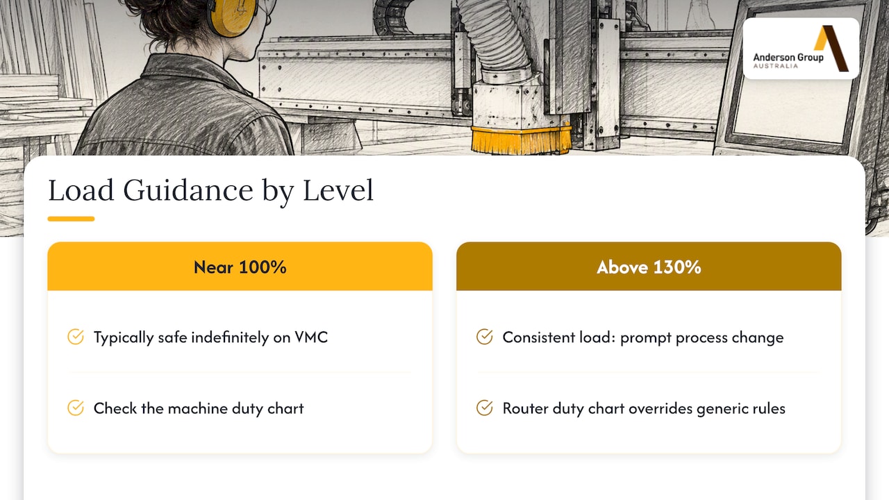
One vendor knowledge base gives rules of thumb for VMC-style machining: loads near 100% are typically safe for indefinite operation, while loads consistently above 130% should prompt a process change such as reducing feed. Treat those figures as a starting reference for a metal-cutting VMC, not as a rule for a woodworking router spindle. Your machine’s own duty chart overrides any generic number.
What this means on a nesting and panel-processing floor
This section is general guidance, not documented Anderson specification. Our customers are mostly kitchen, cabinet, joinery and furniture manufacturers, so it helps to translate the above to sheet-material work.
Spindle load in panel routing is rarely constant. A nested sheet has a mix of conditions that change the load on every pass:
- Full-depth profile cuts around parts, which usually load the spindle most.
- Pocketing, grooving and rebates, with a different engagement and chip evacuation.
- Drilling and light operations, where the load is small and short.
- Air moves, where the spindle is turning but not cutting.
Because of that mix, a single average load figure for a sheet tells you little. Compare the same toolpath operation across sheets: the same profile pass with the same tool, on the same board type. When you do, a creeping rise in load on that operation is a signal worth looking at.
Board variation also matters. Particleboard, MDF, plywood and laminated or melamine-faced sheets all load a tool differently, and batches within one product differ too. If load rises on one batch only, suspect the material before the machine. For machine families and the materials they suit, see our wood machinery range.
Where the data comes from
Controller data
The most direct source is the controller itself. SensFlo states that controller data can expose spindle speed, program state, alarms, part counts and other operating context, but that available signals and connection methods vary by controller. Manufacturers should verify what each machine exposes and whether extra hardware, permissions or configuration are required.
Research published in 2026 argues that intrinsic spindle load signals have an advantage over external sensors: they avoid electrical noise and physical conversion errors, and reflect the machining process more directly.
External sensors on older machines
Where the controller will not give you the data, external sensors are an option. Oak Ridge National Laboratory’s work on low-cost sensors for a digital factory found that current sensors correlated with spindle load. It also found that, when the aim is process monitoring, the sensor should be installed on the spindle drive rather than the machine’s main supply, because the main supply also carries the axes, fans and other loads.
Moving the data into a dashboard
If you want load logged alongside alarms and program state, your options usually involve a standard protocol such as MTConnect or OPC UA. One vendor notes that OPC UA needs an information model that maps machine parameters to nodes, which takes planning. Budget time for that mapping, and for deciding who owns the dashboard once it exists. Our guide to CNC machine monitoring for Australian workshops covers the wider picture of what to track and why.
Setting baselines and alerts that people trust
An alert is only useful if the operators believe it. The way to earn that belief is a baseline built from normal production, not a number lifted from a forum.
- Define the signal. Write down what your controller’s load percentage is scaled against, and whether the log records peaks, averages or sampled values.
- Capture context. xyndata describes capturing spindle load, feed, axis travel, tool usage and alarms from the controller, so a load value can be tied to what the machine was doing.
- Collect a representative window. The same source suggests roughly two to four weeks of operating data to establish each machine’s normal envelope, then continuous updating, with alerts on drift. Treat that as one vendor’s workflow, and extend it if your work mix is seasonal or varies widely.
- Compare equivalent jobs. SensFlo recommends separating setup from production and comparing equivalent jobs and cutting conditions. Material, feed rate, toolpath and operator overrides all move load trends, so rule them out before attributing a change to tool wear.
- Define utilisation honestly. The same source warns that spindle rotation can include air cutting, so state whether you are measuring rotation time or confirmed cutting time, and say what the denominator is.
- Test the idle machine. ORNL recommends periodic idle-spindle-speed tests: calibrate when the machine is healthy, then compare later accelerometer readings with the calibrated values. For repeat production, the first part can act as the calibration cycle.
In a cabinet shop, a practical version of this is a short list of repeat operations (for example, a standard carcass-part profile pass with a given tool). Log the load on those, and review the trend weekly rather than reacting to single sheets.
What spindle load can and cannot tell you
A rising load trend can be consistent with a dulling tool, a change of material, a feed override or a mechanical problem. It cannot say which. Research has proposed using the zero-frequency amplitude and total harmonic distortion of internal load signals as low-cost, sensor-free indicators of tool wear, which is a promising direction, but it is research, not a feature you should assume on your machine.
Use load as one input among several:
- Tool records. Pair load with tool hours or metres cut. Our guide to controller-data tool life monitoring shows how to link the two.
- Part quality. A load change that coincides with edge chipping or dimension drift deserves attention sooner than one that does not.
- Machine health. If load climbs on the same tool and material with no other change, look at the spindle, drive and bearings. The spindle options guide explains what to weigh when specifying one.
- Scheduled maintenance. Monitoring does not replace a routine. See the preventive maintenance checklist for a shop-floor schedule.
Adaptive feed control: acting on load automatically
Some controllers go beyond display. Siemens describes adaptive control that reads tool information from the NC program and continuously monitors spindle load. When it detects overload it reduces feed, and in extreme cases it raises an alarm and stops the machine. Where load is unusually low, it can increase feed.
That is a description of one controller manufacturer’s function, not a statement about any Anderson machine. If automatic feed adjustment matters to your operation, ask us whether the specific model and controller you are considering supports it, rather than assuming it from the machine family.
Metal and advanced materials: a separate case
The load figures quoted in most published guidance come from metal-cutting machines, where spindle torque, coolant and tool engagement behave very differently from sheet routing. If you are cutting metal or aluminium, thresholds and drift behaviour should be developed for that process on its own. Our metal machinery range covers those machines. Compatibility questions, such as coolant, probing or pallet changing, need to be confirmed against the exact model, as they cannot be inferred from a family name or axis count.
Questions to ask before you buy a machine
If load data matters to you, put it in the specification conversation. Good questions for any supplier, including us:
- Which spindle load, torque and power signals does this exact model and controller expose?
- How is the percentage scaled: against power at current rpm, or peak continuous power?
- Can the data be logged, exported or read over a standard protocol, and does that need extra hardware or licences?
- Where are the spindle’s power and torque charts and duty ratings documented?
- What happens on overload: warning only, feed reduction or stop?
- Which service and parts arrangements apply once the machine is running? Confirm the agreed scope in writing.
It also helps to read about reliability checks before committing. Our guide on verifying CNC reliability with a 90 day plan sets out checks you can apply at acceptance, and the piece on improving CNC uptime looks at what drives lost machine hours.
Talk to us about your application
Anderson Group Australia supplies CNC machinery, servicing and parts to Australian manufacturers, with a primary focus on kitchen, cabinet, joinery and furniture production. We match woodworking and nesting applications to Anderson machines, and metal and aluminium milling to Focaseiki. We help you choose machinery for your own production; we do not offer subcontract cutting or machining.
If you are comparing machines and want to know what each exposes for monitoring, start at our machines range, then contact us through Anderson Group Australia with your materials, sheet volumes and monitoring needs. We will check specifications against the relevant product page and discuss your application or a quote.
FAQ
Is a spindle load of over 100% bad?
Not necessarily. The meter can spike well above 100% during spindle acceleration, and some controllers scale against continuous rather than peak ratings. What matters is sustained load during cutting, read against the motor’s duty chart in your machine documentation.
Can I compare spindle load between two machines?
Only with care. Signal definition, scaling and recording behaviour vary by system and manufacturer, so the same cut can show different percentages. Compare trends on one machine, one tool and one material instead.
Do I need external sensors to monitor spindle load?
Not if the controller exposes the data you need. External current sensors are an option for older machines where internal data is not accessible, and they are best fitted to the spindle drive rather than the main supply.
How long does it take to set a useful baseline?
One vendor workflow suggests roughly two to four weeks of operating data per machine, then continuous updating. Shops with varied work may need longer, and the baseline should only compare equivalent jobs.
Sources
- CNC Spindle Load Meter: Reading VMC Over-100% Loads
- Tips for Monitoring Spindle Loads and Cutting Stability
- Spindle Load, Load Controls
- Spindle-Load Monitoring: Define the Signal Before You Use It
- CNC Machine Monitoring for Job Shops
- Research on ACZF and THD of machine tool spindle load
- Low-cost sensors and analytics for a digital factory, Oak Ridge National Laboratory
- CNC Machine Data Collection: MTConnect vs OPC UA
- Predictive Maintenance for CNC Machines
- Machining with Feeling: Adaptive Control & Monitoring