
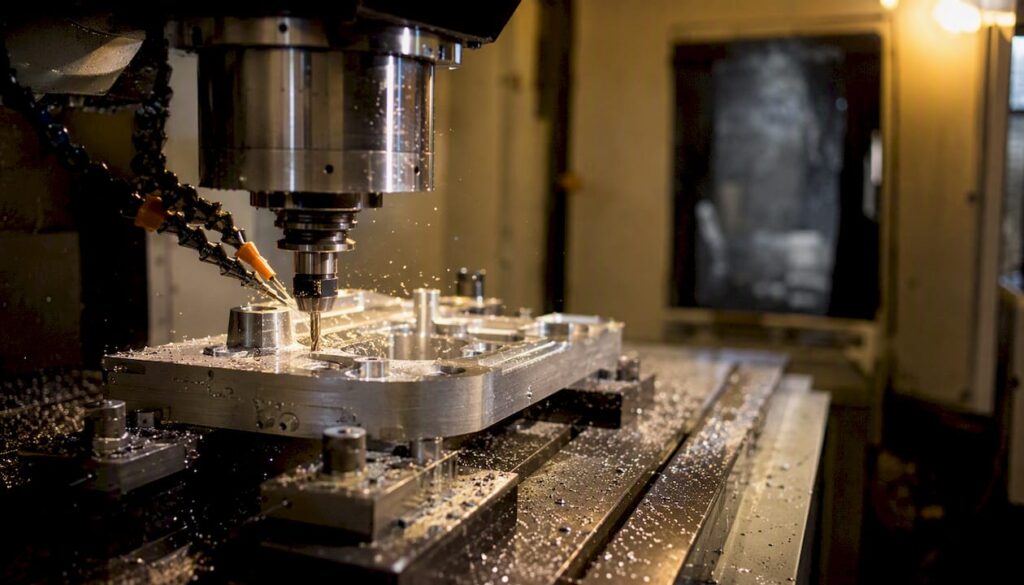
Aerospace CNC machining is the controlled, traceable production of flight-critical components on multi-axis CNC centres, backed by rigorous NC-code verification and documented inspection to meet standards such as AS9100. Get the definition right and the specification follows: a five-axis blisk, a landing-gear fitting, and a titanium actuator housing all demand the same non-negotiable trio of controls, even though the geometry, material and tolerance band differ widely.
Before you release a drawing or send an RFQ, put these on the purchase order:
- Tolerance banding stated per feature, not as a single blanket figure across the whole part.
- Material traceability back to heat and lot number, with certs supplied before machining starts.
- On-machine probing (Renishaw OMP600 or equivalent) built into the process, not bolted on afterwards.
- NC verification through software such as VERICUT before a single chip is cut.
- First article inspection (FAI) reported against every characteristic on the drawing, not a sample set.
Miss any one of these and the cost of failure escalates fast. A single unverified post-processor error can send a five-axis head into a fixture at full feed, and the repair bill for a wrecked spindle and toolholder routinely runs into six figures before you even count the delay to the production schedule. That is why verification isn’t a formality on flight-critical work. It’s the thing standing between a good part and a grounded aircraft.
Key Takeaways
Aerospace CNC machining succeeds when verification, traceability and machine capability are all specified as rigorously as the tolerance band itself.
| Point | Details |
|---|---|
| Verify NC code before cutting | Simulate every program in VERICUT or an equivalent tool to catch collisions and post-processor errors before they reach the machine. |
| Demand full traceability | Require material certs, heat-treatment records and lot traceability on every purchase order for flight-critical parts. |
| Match machine to geometry | Reserve simultaneous five-axis capability for blended surfaces like blisks; use 3+2 for most other features. |
| Plan inspection from the start | Build CMM, in-process probing and FAI requirements into the drawing, not as an afterthought at final inspection. |
| Anderson supports the full workflow | Anderson’s five-axis and production machining centres pair rigidity and probe integration for aerospace-grade repeatability. |
Table of Contents
- Why precision aerospace machining matters more than most manufacturing
- What aerospace components actually get CNC machined
- Which CNC processes and machines suit aerospace work
- Which materials give aerospace machinists the most trouble
- How tolerances and inspection are controlled on aerospace parts
- How CAM planning and NC verification prevent costly mistakes
- Design-for-manufacturing rules that cut cost and risk
- What drives aerospace machining cost and lead time
- Which certifications actually determine supplier selection
- What to demand from a machining supplier and their equipment
- Why heat treatment after machining changes the tolerance conversation
- Where aerospace materials commonly go wrong on the machine
- How coolant, chip management and operator safety fit into the process
- Why I still insist on verification-first specifications
- How Anderson supports aerospace-grade machining programs
- Sources
Why precision aerospace machining matters more than most manufacturing
Aerospace parts fail differently to almost anything else you’ll machine. A tolerance miss on a bracket for industrial equipment might mean a squeak or a slightly loose fit. The same miss on a hydraulic actuator body or a turbine disc can mean a fatigue crack that propagates over thousands of flight cycles and ends in a component failure at 35,000 feet.
That’s the real argument for tight process control, and it breaks down into four practical concerns:
- Airworthiness: every dimension on a flight-critical part ties back to a certified design, and any deviation has to be documented and dispositioned, not just noted and ignored.
- Repeatability: production runs of hundreds or thousands of identical parts need a process that produces the same result on part one and part one thousand.
- Weight and aerodynamic fit: aerospace components are engineered to the gram, so machining strategies that hold true position across a whole airframe matter as much as raw dimensional accuracy.
- Serviceability: bearing fits, sealing surfaces and interface tolerances directly determine how long a component lasts in service before it needs replacement.
A five-axis blisk machining study found that analysing cutting forces and refining the toolpath cut total machining time by roughly 16.5% after the feed rate was increased by 20%. That’s not a minor efficiency gain. It’s the difference between a process that’s merely accurate and one that’s accurate and commercially viable on a real production schedule.
What aerospace components actually get CNC machined
Most engineers picture turbine blades when they hear “aerospace machining,” but the real variety of parts crossing a CNC shop floor is broader. Each part type has its own process requirements and inspection needs.
- Turbine blades and blisks require simultaneous five-axis milling in a single setup, as their blended aerofoil surfaces cannot be reached otherwise; inspection typically includes CMM plus blade-profile scanning.
- Fan discs and rotating shafts are usually turned first, then finish-milled for slots and features, with runout and balance tolerances influencing inspection.
- Structural housings and hydraulic bodies often utilize 3+2 positioning on several faces, since many features lie on flat or near-flat planes.
- Landing-gear fittings involve heavy-duty turning and milling in high-strength steels, with fatigue-critical bores requiring thorough CMM traceability.
- Actuator bodies and avionics housings often run on 3-axis or 3+2 machines but maintain tight positional tolerances on mounting faces and seal grooves.
- Thin-wall structural ribs need specialized fixture design and finishing to control deflection, favoring five-axis strategies despite simple geometry.
Blisks, impellers and complex aerofoil geometry are commonly outsourced to AS9100-certified specialists with established simultaneous five-axis programs due to substantial programming and verification requirements. Simpler housings and brackets are often managed in-house where capable 3+2 or vertical machining centers exist.
Which CNC processes and machines suit aerospace work
Choosing the right process starts with understanding what each configuration actually buys you. 3-axis milling handles flat and prismatic features economically, and it’s still the right call for a huge share of bracket and housing work. 3+2 positioning, where the machine indexes to a fixed angle and then cuts in three axes, covers an estimated 80% of aerospace shop work, because most parts don’t genuinely need continuous multi-axis motion.
Simultaneous five-axis machining earns its keep on blisks, impellers and blended aerofoil surfaces where the tool needs to stay normal to a continuously curving surface. It can machine complex contours in a single setup, and industry guidance on aerospace five-axis work cites achievable tolerances around ±0.005mm on curved surfaces, largely because eliminating repeated setups removes the positioning error that stacks up every time a part gets unclamped and re-fixtured.
Machine architecture matters here too. Trunnion-table machines tilt the part, which suits smaller components and gives excellent rigidity. Swivel-head configurations move the tool instead, which suits larger or heavier workpieces where re-orienting the part isn’t practical. Anderson’s AXXIOM five-axis series and the larger-format MASS-5 machining centre both address this tradeoff, with the required workholding, loading and any pallet-changing options confirmed for the exact model and application.
Verification hardware is just as important as the cutting axes. On-machine probes like the Renishaw OMP600, laser tool setters, and spindle displacement sensors let a machine check its own work mid-cycle and compensate for thermal drift or tool wear before it becomes a scrap part.
Which materials give aerospace machinists the most trouble
Material choice drives tool selection, cycle time and cost more than almost anything else in the spec. Get the machinability wrong at the quoting stage and you’ll blow the budget before the first part comes off the machine.
- Aluminium alloys (2024, 7075) machine fast and forgiving, but thin-wall aerospace geometry still needs careful fixturing to control deflection and chatter.
- Titanium alloys (Ti-6Al-4V) have poor thermal conductivity, so heat concentrates at the cutting edge instead of dissipating into the chip, driving rapid tool wear and work hardening if feed rates drop too low.
- Stainless steels work harden quickly under interrupted cuts, which pushes shops towards consistent chip loads and sharp, uncoated or PVD-coated tooling.
- Nickel superalloys like Inconel 718 chew through carbide tooling at a rate that makes tool cost a genuine line item in the quote, and they demand rigid setups with high-pressure coolant delivery.
- Advanced composites risk delamination and fibre pull-out unless cutting parameters and tool geometry are matched specifically to the layup.
- High-performance polymers such as PEEK machine cleanly but generate heat that can distort thin sections if cooling isn’t managed.
Pro Tip: On titanium and Inconel, trochoidal milling strategies (a looping toolpath that keeps radial engagement low) let you run higher cutting speeds without spiking cutting temperature, and they cut tool wear dramatically compared with conventional slotting passes.
How tolerances and inspection are controlled on aerospace parts
Aerospace tolerance bands vary enormously by feature, and treating every dimension the same is one of the most expensive mistakes an engineer can make on a drawing. Non-critical envelope dimensions might sit at ±0.1mm, while bearing bores, sealing faces and blade profiles routinely fall into ranges as tight as ±0.0001 to ±0.001 inches for the features that matter most functionally.
Getting there requires a layered inspection strategy rather than a single check at the end of the run.
| Inspection method | Feature type | Recommended sampling |
|---|---|---|
| CMM coordinate measurement | Critical bores, datums, complex profiles | 100% on FAI, statistical sampling in production |
| In-process probing | Feature location, tool wear compensation | Every cycle or every batch |
| Profilometry | Sealing faces, bearing surfaces | Per lot, tied to surface finish spec |
| NDT (dye penetrant, ultrasonic) | Fatigue-critical castings and forgings | Full inspection on flight-critical parts |
| Laser scanning | Aerofoil and blended surfaces | FAI plus periodic production audit |
Documentation ties the whole picture together: material certificates, heat-treatment records, lot traceability, CMM reports and complete FAI packages. AS9100 governs the quality management system a supplier must run, while NADCAP accredits specific special processes like heat treatment, welding and non-destructive testing. Together they give an OEM a way to audit a supplier’s process without inspecting every part personally, which is exactly why they show up as gatekeeper requirements on most aerospace purchase orders.
How CAM planning and NC verification prevent costly mistakes
Every aerospace program lives or dies on the gap between the CAM model and what the machine actually does. Skip a verification step and you’re gambling a $40,000 titanium forging on the hope that nobody made a typo in the post-processor.
- Build and review the toolpath in CAM software such as Siemens NX (including NX10), hyperMILL or Mastercam, checking feed rates, stepovers and tool engagement against the material.
- Generate the post-processor output specific to the target machine’s kinematics, not a generic G-code dialect.
- Simulate the full NC program in VERICUT or an equivalent verification tool to catch collisions, over-travel and post-processor errors before the machine ever sees the file.
- Run a dry cycle with the tool retracted or at safe height to confirm motion sequencing matches the simulation.
- Cut the first article at reduced feed and speed, with in-process probing checking critical features before committing to full production rates.
- Compare the FAI report against the drawing, feature by feature, before releasing the program for production runs.
On simultaneous five-axis work specifically, watch for singularities: points where rotary axes align and a small programmed move translates into a violent physical axis jump. Post-processor axis limits and a proper machine kinematic model in the simulation catch this before it damages a spindle or fixture.
Pro Tip: The most common post-processor failure isn’t a crash, it’s a silently wrong tool length offset. Always verify offsets against the physical tool assembly, not just the CAM model’s assumed values.
Sensory tool holders and on-machine probing during rough and finish passes let the machine measure cutting force and compensate in real time, which is the same mechanism behind that 16.5% cycle-time reduction on blisk work. Verification isn’t just a safety net. It pays for itself in feed rate.
Design-for-manufacturing rules that cut cost and risk
The cheapest tolerance to hold is the one you never had to specify. Good DFM practice on aerospace parts starts at the design review, not at the CAM stage.
- Minimise the number of setups by grouping features that can be machined from a common orientation.
- Place datums where a CMM probe or on-machine probe can actually reach them, not buried inside a pocket.
- Avoid deep, narrow internal features that no standard measurement tool can verify.
- Allocate tight tolerances to the assembly interface, not to every individual part dimension, unless the function genuinely demands it at the part level.
- Flag secondary operations like grinding, honing or lapping explicitly on the drawing rather than leaving them implied.
A short DFM checklist worth pasting straight into a drawing template:
- Can every toleranced feature be measured with available CMM or probing equipment?
- Have setups been minimised, and is the datum scheme consistent across all operations?
- Are tolerance stacks allocated sensibly between part-level and assembly-level requirements?
- Are secondary operations (heat treatment, plating, grinding) called out with sequence and spec?
- Have thin-wall or deflection-prone features been flagged for special fixturing?
What drives aerospace machining cost and lead time
Material cost sets the floor. Titanium and Inconel billet can cost many times more than aluminium per kilogram, and that gap widens further once you account for the tool wear each material causes. Complexity is the next lever: simultaneous five-axis programming for a blisk or impeller can take three to five times longer to program than an equivalent 3+2 setup, though that overhead is usually recovered across a production run once tolerance stack-up and setup time disappear.
Inspection and certification overhead adds up fast too. FAI reporting against every drawing characteristic, CMM programming, and NADCAP special-process paperwork all take real hours before a part ships. Volume changes the economics again: a one-off prototype absorbs the full weight of programming and first article inspection, while a production run of several hundred parts spreads that cost thin.
A realistic project timeline runs roughly: design finalisation, then CAM programming and simulation, then verification and dry runs, then first article inspection, then release to full production. Compressing that sequence by skipping verification steps almost always costs more later in scrap and schedule slip than it saves upfront.
Which certifications actually determine supplier selection
AS9100 is the aerospace-specific quality management standard built on top of ISO 9001, adding requirements around risk management, configuration control and traceability that general manufacturing certification doesn’t touch. NADCAP accredits special processes: heat treatment, welding, non-destructive testing, chemical processing and coatings, and it’s typically required whenever a part goes through one of those processes as part of its build.
When you write a purchase order for an aerospace part, request the supplier’s current AS9100 certificate, confirm NADCAP scope covers any special process the part requires, and specify that material lot traceability and a complete FAI package accompany the shipment. A supplier’s AS9100D certification and explicit traceability for material lots, heat treatment and FAI packages is often the single factor that determines whether they make it onto an OEM’s approved supplier list at all. These certifications exist precisely to cut the audit burden an OEM would otherwise carry for every supplier relationship.
What to demand from a machining supplier and their equipment
Choosing a supplier for aerospace work comes down to a short list of hard questions, and it’s worth asking them before the first quote, not after the first missed delivery.
- Does the supplier hold current AS9100 certification, and NADCAP accreditation for any special process the part needs?
- Can they demonstrate CMM and on-machine probing capability, ideally with Renishaw or equivalent hardware integrated into the machining cycle?
- Do they have a proven program history machining titanium or Inconel, not just aluminium?
- Will they supply a sample FAI package before committing to a production order?
On the machine side, match capability to geometry rather than buying more axis count than the part needs:
- Confirm simultaneous five-axis capability only where the geometry genuinely requires it, such as blended aerofoil surfaces.
- Check whether a trunnion-table or swivel-head configuration suits the part size and weight better.
- Verify spindle power and structural rigidity against the material, since Inconel and titanium punish underpowered spindles.
- Ask about thermal control measures, since dimensional drift from spindle heat is a common source of out-of-tolerance parts on long production runs.
- For production volumes, confirm auto pallet change capability to hold cycle-to-cycle consistency without manual intervention.
Machines like Anderson’s MASS-B enclosed five-axis centre and the production machining centre with auto pallet changer are built around exactly this brief: enough rigidity and thermal stability for demanding materials, with the automation to keep a production run consistent from the first part to the last.
Why heat treatment after machining changes the tolerance conversation
Heat treatment doesn’t just change hardness. It changes dimensions, and if that’s not planned for, a part that passed inspection before treatment can fail after it. Stress relief cycles on titanium and nickel superalloys relieve residual machining stresses that would otherwise cause distortion once the part is in service, but the relief itself can move critical features by measurable amounts.
That’s why aerospace process plans commonly split machining into two stages: rough and semi-finish before heat treatment, then a finish pass afterwards on the features with the tightest tolerances. Bearing bores, sealing faces and mating surfaces almost always get machined last, after the part has already moved through whatever dimensional shift the heat cycle causes. Skipping this sequencing is one of the most common (and expensive) mistakes on new aerospace programs, because it shows up as a run of out-of-tolerance parts only after the heat treatment batch comes back from a NADCAP-accredited processor.
Where aerospace materials commonly go wrong on the machine
Every aerospace material has its own signature failure mode, and recognising it early is what separates a smooth production run from a scrap pile.
Titanium work hardens the moment feed rate drops too low or the tool starts to dull, which is a vicious cycle: a hardened surface accelerates further tool wear, which drops cutting efficiency further still. The fix is consistent chip load, sharp tooling changed on a schedule rather than run to failure, and high-pressure coolant directed right at the cutting edge.
Inconel and other nickel superalloys chew through carbide inserts fast enough that tool cost becomes a real line item, and the usual mitigation is ceramic or coated carbide tooling run at lower speeds with rigid setups to prevent chatter, which itself accelerates wear.
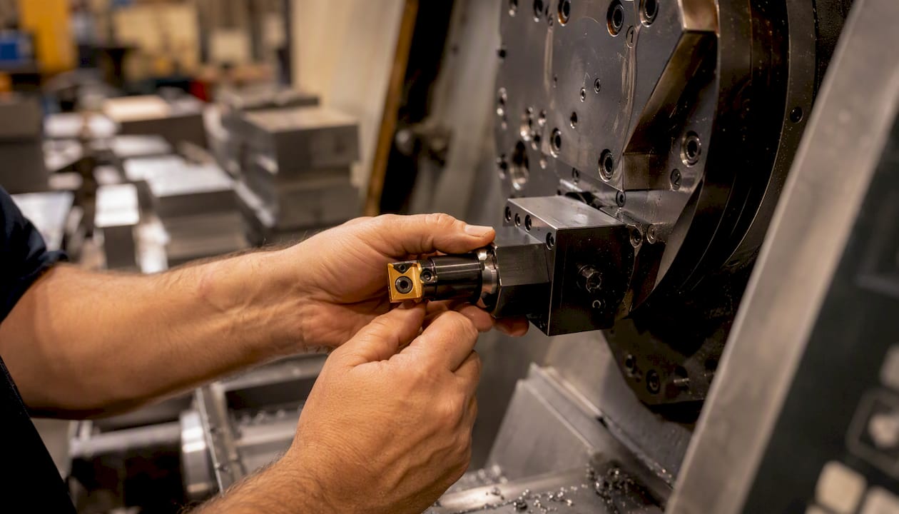
Composites risk delamination at the exit side of every cut unless the tool geometry and feed direction are matched to the fibre layup, and diamond-coated or PCD tooling reduces the fibre pull-out that plain carbide tools cause.
Thin-wall structural parts in any material deflect under cutting force, and the recommended mitigation is alternating side machining with reduced depth stepdowns near the free edge, sometimes backed by temporary low-melt wax support to suppress vibration during finishing.
How coolant, chip management and operator safety fit into the process
Aerospace machining generates real environmental and safety exposure that a process plan has to account for, not just the cutting parameters. Titanium chips are a genuine fire risk, since fine titanium swarf can ignite under certain conditions, so shops running titanium need dedicated chip extraction and disposal procedures separate from steel or aluminium waste streams.
Coolant selection matters both for machining performance and for exposure control. High-pressure coolant systems needed for Inconel and titanium machining produce fine mist that requires proper extraction to protect operators from prolonged exposure, and used coolant carrying metal fines needs to be filtered and disposed of through a licensed waste handler rather than down a drain. Enclosed machining centres, such as Anderson’s MASS-B configuration, help contain both the mist and the swarf, which matters more on titanium and composite work than on aluminium.
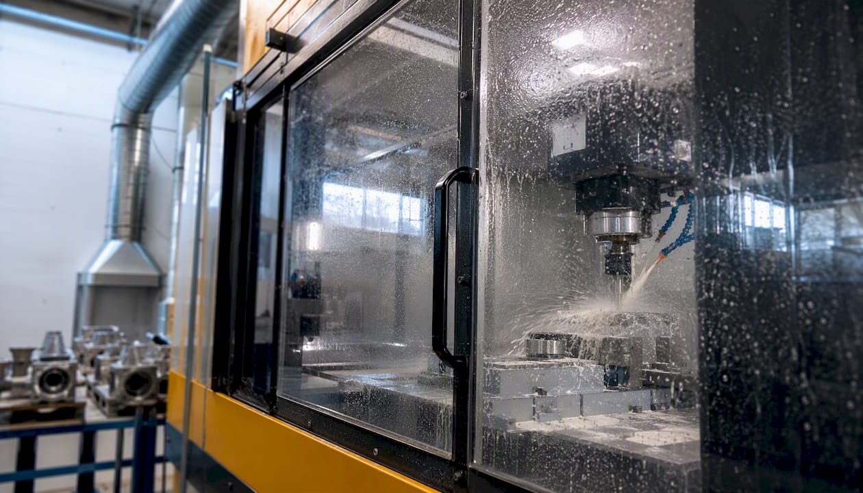
Operator safety around automated pallet changers and multi-axis motion adds another layer: proper machine guarding, interlocks, and training on singularity risk near trunnion tables all belong in a shop’s standard operating procedure, not left to individual operator judgement.
Why I still insist on verification-first specifications
Every aerospace program I’ve reviewed that ran into trouble had the same root cause: someone treated verification as a checkbox rather than a discipline. The engineering community talks a lot about tolerance bands and material selection, and both matter, but the conversations that actually prevent scrap and schedule slip happen around the CAM simulation screen, not the drawing review.
The uncomfortable truth is that most aerospace machining failures aren’t material problems or geometry problems. They’re process control problems, dressed up afterwards as something more technical. A part that comes back out of tolerance almost always traces to a probing step that got skipped, a post-processor that wasn’t checked against the actual machine kinematics, or an FAI report that got rubber-stamped instead of genuinely audited feature by feature. Specify the verification workflow with the same rigour you specify the tolerance band, and the tolerance band takes care of itself.
How Anderson supports aerospace-grade machining programs
Specifying the right process is only half the job. Running it on a machine that can actually hold the tolerance band, cycle after cycle, is the other half. Anderson builds five-axis and heavy-duty machining centres engineered for exactly the demands this guide has covered: simultaneous five-axis capability for blisk and blended-surface work, on-machine probe integration for in-process verification, and the rigidity to handle titanium and Inconel without chasing thermal drift all shift.

The AXXIOM five-axis series and the larger-format MASS-5 centre are built for shops moving complex aerospace geometry from prototype into production, with handling, workholding and any automation options specified for the exact machine and production task. For operations spanning multiple materials, from aluminium airframe brackets through to metalwork requiring higher rigidity, Anderson’s industries overview outlines how machine selection maps to the aerospace, automotive and general engineering sectors it serves. If you’re specifying a machine for an aerospace program right now, get in touch through Anderson’s main site to talk through spindle power, workpiece envelope and probing integration against your actual part list.
Sources
The following sources back the technical claims in this guide and are worth reading directly if you’re drafting a specification or auditing a supplier.
- PMC article on five‑axis blisk machining and force analysis
- Aerospace 5 axis machining: a complete guide to processes, special materials, and compliance — CNC Protolabs
- Aerospace precision machining: complete guide to tolerances, materials, inspection & supplier selection — UneedPM
- 5‑Axis aerospace CNC programming — HymsonLaser