
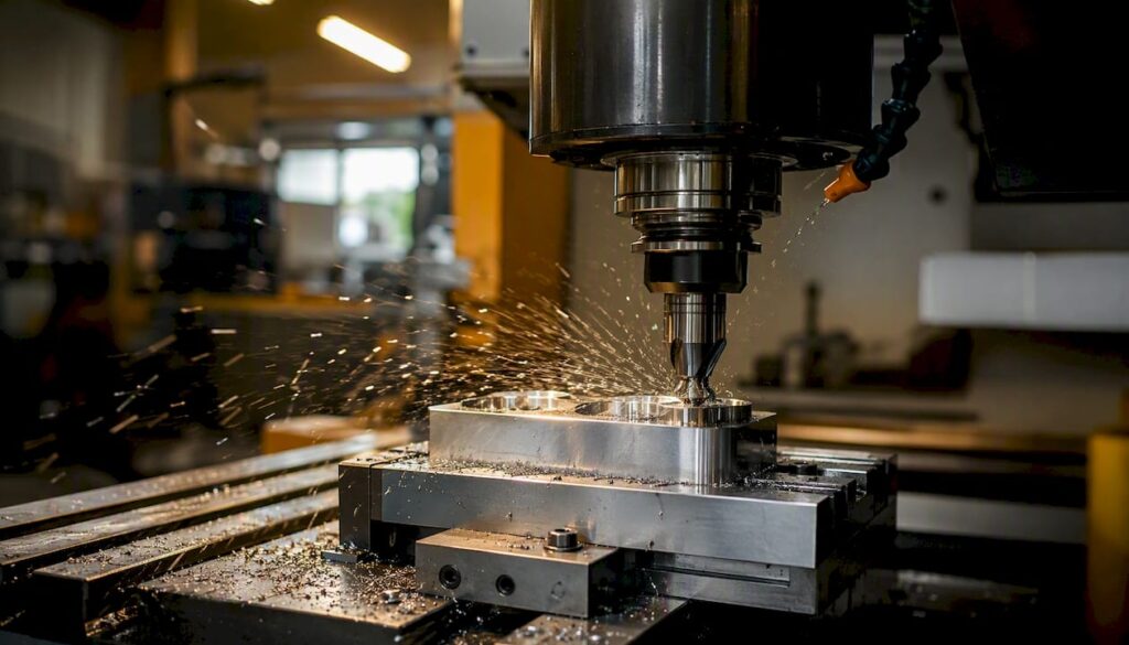
High speed machining (HSM) delivers faster cycle times, better surface finishes, and more predictable tool life by combining very high spindle speeds with shallow depths of cut and controlled radial engagement — not by simply cranking up the RPM on a conventional setup. As a system-level approach, HSM requires the machine, tooling, CAM strategy, and fixturing to work together. Get that right, and the productivity gains are real.
Three things engineers need to know immediately:
-
Best-fit parts: Complex 3D contours, thin-walled components, tight-tolerance moulds, and high-value aerospace or medical parts — not bulk roughing of large steel billets.
-
Cycle-time gains: Correctly implemented HSM can reduce cycle times substantially on suitable parts, particularly aluminium and non-ferrous alloys machined at spindle speeds of 15,000–40,000+ RPM.
-
Primary machine requirements: High-rigidity frame, thermally stable spindle, advanced look-ahead controller, and balanced toolholders — Anderson Group Australia supplies machining centres built to these specifications.
Key takeaways
HSM delivers its best results when machine rigidity, spindle speed, adaptive CAM toolpaths, and balanced tooling are treated as a single integrated system — not as independent variables.
| Point | Details |
|---|---|
| HSM is a system, not a setting | Machine, spindle, CAM, and tooling must all be matched; changing one parameter alone rarely delivers the expected gain. |
| Start with adaptive clearing | Adaptive or constant-engagement toolpaths are the fastest route to stable HSM on a new part; use them for roughing before refining finishing passes. |
| Validate with a test cut | Run at 50% feed override, inspect chip form and finish, then step up — never trust handbook values without a validation cut on your specific setup. |
| Aluminium is the easiest entry point | At — m/min surface speed and 15,000–40,000 RPM, aluminium HSM delivers the clearest cycle-time and finish gains with the lowest tooling risk. |
| Anderson for implementation | Anderson’s STRATOS, AXXIOM, and MASS-5 machining centres are built to the spindle speed, rigidity, and controller specifications that HSM requires. |
Table of Contents
What is high speed machining and how does it differ from conventional milling?
The term gets misused constantly. HSM is not conventional milling with the feed override pushed to 120%. It is a fundamentally different philosophy of how the cutter engages the workpiece.
In conventional milling, you take a deep axial cut at moderate speed and accept high cutting forces. The cutter spends a large proportion of each revolution in contact with the material. Chips are thick, heat builds in the tool, and the machine structure absorbs significant force variation. In HSM, the axial depth of cut (DOC) drops dramatically, radial engagement is kept narrow and consistent, and spindle speed rises to compensate — keeping the metal removal rate (MRR) competitive while cutting forces per tooth stay low. The Seco Tools guide on HSM frames it well: higher cutting speeds combined with high feed rates and lighter cuts improve surface finish and metal removal efficiency when the whole system is optimised.
Key glossary terms:
-
SFM / m/min (surface feet per minute / metres per minute): The speed at which the cutter’s edge moves through the material. HSM targets the upper end of the recommended range for each material.
-
Chip thickness per tooth (fz): The amount of material each flute removes per revolution. In HSM, fz is deliberately kept low — often 0.01–0.05 mm for finishing passes — but feed rate stays high because RPM is elevated.
-
Axial depth of cut (ap): The depth the cutter engages along its axis. HSM typically uses ap values of 0.1–1× the cutter diameter, depending on material and strategy.
-
Radial engagement (ae): How much of the cutter’s diameter contacts the workpiece. Trochoidal and adaptive strategies keep ae at 5–15% of cutter diameter to maintain consistent chip load.
Think of it this way: conventional milling is a heavy push; HSM is a rapid, controlled peel. The chip formation changes, heat transfers into the chip rather than the tool, and the surface left behind is cleaner.
What are the primary benefits and applications of HSM?
Where HSM delivers the biggest return
-
Cycle time reduction: Shallower cuts at higher feed rates often outpace conventional strategies on complex geometries, particularly 3D contoured surfaces where a ball-nose or bull-nose cutter is making many light passes.
-
Surface finish: Lower cutting forces mean less deflection, which translates directly to better dimensional accuracy and surface quality — often eliminating or reducing hand-finishing and polishing steps.
-
Dimensional repeatability: Consistent chip load and lower thermal input reduce workpiece distortion, which matters enormously on thin-walled parts and precision housings.
-
Tool life: Counter-intuitively, shorter tool contact time per revolution at controlled chip thickness can extend tool life compared with aggressive conventional cuts that overheat the edge.
-
Reduced secondary operations: Better as-machined finishes mean fewer benching, polishing, or EDM steps downstream.
Industries and part types that benefit most
-
Aerospace structural brackets and monolithic frames (aluminium 7075, titanium Ti-6Al-4V)
-
Medical implants and surgical instruments requiring tight tolerances and excellent surface integrity
-
Injection moulds and die-cast tooling where surface finish directly affects part quality
-
Electronics housings and heat sinks in aluminium or magnesium alloy
-
Thin-walled components where conventional forces would cause deflection or chatter
Cycle-time note: Research on HSM applications indicates that when correctly applied to aluminium and other non-ferrous alloys, HSM can deliver substantial cycle-time reductions and improved finishes. Specific gains depend on part geometry, material, and machine capability — treat published percentage claims as directional, not guaranteed.
What machine and system capabilities does HSM require?
HSM puts demands on every part of the machine. A capable spindle on a flexible frame will chatter. A rigid frame with a slow controller will produce poor surface quality at high feed rates. All four system elements — machine structure, spindle, controller, and workholding — need to be matched.
Machine structure
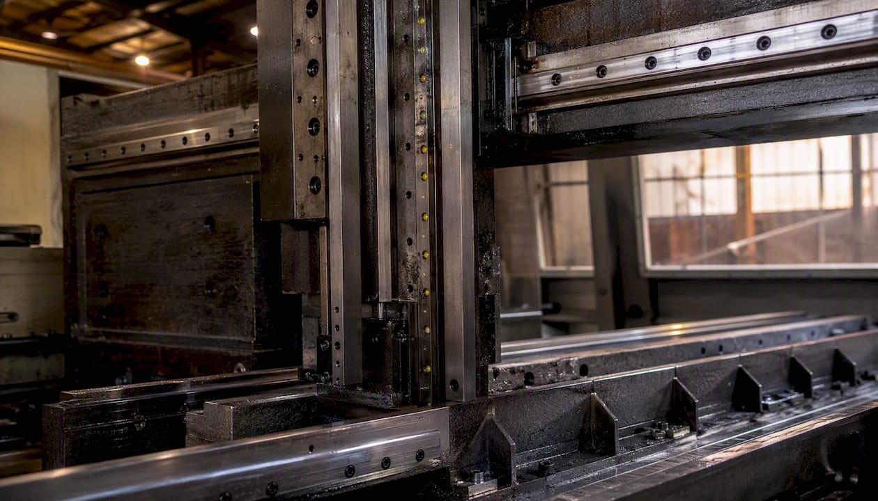
Stiffness is the foundation. The column, bed, and table must resist the dynamic forces generated at high feed rates without deflecting. Low-inertia moving components (lightweight spindle heads, linear guides rather than box ways in some configurations) allow the machine to accelerate and decelerate quickly between direction changes without overshooting. Thermal stability matters too: spindle growth from heat can shift a bore by several microns over a shift, so machines designed for HSM incorporate thermal compensation systems or oil-cooled spindle housings.
Spindle design
For aluminium and non-ferrous work, spindle speeds of 20,000–40,000 RPM are common. Hardened steel and titanium typically run lower (8,000–15,000 RPM) but still benefit from HSM strategies. Bearing types matter: angular contact ceramic bearings handle high-speed loads better than standard steel bearings. Direct-drive or integrated motor-spindle designs eliminate belt-drive compliance. Oil-air lubrication keeps bearings cool at sustained high RPM. Spindle power under load is equally important — a 20,000 RPM spindle that drops to 15,000 RPM under cut is not delivering HSM.
Controller and CAM
Advanced controllers with look-ahead and jerk control are non-negotiable for HSM. Look-ahead allows the controller to read upcoming toolpath geometry and pre-emptively adjust feed rate before a corner or direction change — without it, the machine decelerates reactively, creating dwell marks and force spikes. Jerk control smooths acceleration curves to prevent resonance. On the CAM side, adaptive toolpath algorithms (Mastercam Dynamic Motion, Fusion 360 Adaptive Clearing, Hypermill MAXX Machining) generate paths that maintain constant chip load regardless of geometry changes.
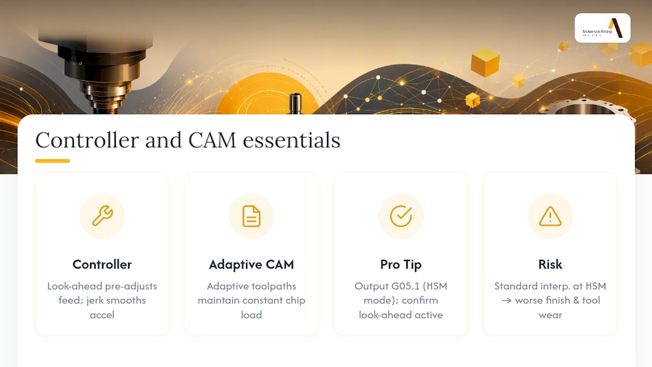
Pro Tip: Set your CAM post-processor to output G05.1 (or the equivalent high-speed mode for your controller) and confirm look-ahead is active before running any HSM program. A controller running in standard interpolation mode at HSM feed rates will produce a noticeably worse finish and higher tool wear.
Which CAM toolpath strategies work best for HSM?
The toolpath is where HSM theory becomes shop-floor reality. Choosing the wrong strategy — even on a capable machine — wastes the investment.
Core strategies
-
Adaptive clearing (constant-load): Maintains a fixed radial chip load by continuously adjusting the path as the cutter moves through the pocket. This is the go-to roughing strategy for HSM because it eliminates the force spikes that occur when a conventional path drives the cutter into a corner at full engagement. Adaptive and constant-engagement toolpaths are often the fastest route to stabilising a high-speed process on real parts.
-
Trochoidal milling: The cutter follows a circular looping path that limits radial engagement to a small arc, even in narrow slots. Particularly effective for slotting operations where a conventional path would bury the cutter at 100% engagement.
-
High-feed milling (HFM): Uses a shallow axial DOC (often 0.3–0.8 mm) with very high feed rates. The cutting geometry redirects forces axially rather than radially, reducing deflection. Best suited to roughing passes on harder materials.
-
Radial chip-thinning strategies: When ae drops below 50% of cutter diameter, the actual chip thickness is less than the programmed fz. Chip-thinning compensation increases the programmed feed rate to maintain the target chip thickness — without it, you are under-loading the cutter and wasting cycle time.
-
Constant-scallop finishing: Maintains a uniform scallop height across a 3D surface by varying stepover based on local curvature. Produces consistent surface quality without manual stepover adjustments.
Entry, exit, and cornering
Ramp or helical entry into pockets keeps the cutter from plunging at full diameter. At corners, the toolpath should arc rather than make a sharp direction change — a sharp corner forces the cutter to decelerate, dwell, and then accelerate, leaving a witness mark and spiking the chip load. Most CAM packages handle this automatically when corner smoothing is enabled.
Pro Tip: Minimise the number of direction reversals in your toolpath. Every reversal is a deceleration-acceleration event that costs time and stresses the spindle bearings. Spiral-out or one-way finishing passes on flat surfaces are faster and produce better finishes than back-and-forth raster paths.
Cutting parameters: starting values and worked examples
Optimised toolpaths and chip-thinning strategies lower cutting forces and enable higher feed rates — but you still need a sensible starting point before you iterate.
Starting parameter ranges by material
D = cutter diameter. Values are starting points for solid carbide end mills with TiAlN coating; adjust based on trial cuts and chip inspection.
Worked example: aluminium at 400 m/min
You have a 10 mm solid carbide end mill and want to run at 400 m/min surface speed.
-
Calculate RPM: RPM = (1,000 × vc) ÷ (π × D) = (1,000 × 400) ÷ (3.1416 × 10) = 12,732 RPM
-
Set fz: Start at 0.05 mm per tooth for a 4-flute cutter.
-
Calculate feed rate: Vf = fz × z × n = 0.05 × 4 × 12,732 = 2,546 mm/min
-
Apply chip-thinning correction: If ae = 1.5 mm (15% of 10 mm D), the chip-thinning factor = √(D ÷ (2 × ae)) = √(10 ÷ 3) = 1.83. Corrected feed = 2,546 × 1.83 = 4,659 mm/min
-
Set ap: Start at 0.5× D = 5 mm for roughing; reduce to 0.1× D for finishing.
Run a short validation cut, inspect chip colour (silver to light gold is correct for aluminium; blue or black means too much heat), and adjust from there. Aluminium HSM often operates above 20,000 RPM with short tool stick-out and balanced holders to avoid chatter — so if your machine has the spindle speed, push the surface speed toward 500–600 m/min and recalculate.
How do you choose and maintain tooling for HSM?
Tooling selection
-
Solid carbide end mills: The baseline for HSM. Indexable tooling is too heavy and unbalanced for high-RPM operation in most cases.
-
Variable flute geometry (variable helix/pitch): Disrupts the harmonic frequency that causes chatter. Worth the cost premium on any HSM application.
-
Coatings: TiAlN for steel and titanium (handles heat well); AlTiN for very high-temperature cuts; DLC (diamond-like carbon) for aluminium and non-ferrous to prevent built-up edge.
-
Tool length and stick-out: Keep stick-out to 3–4× cutter diameter maximum. Every additional millimetre of stick-out reduces stiffness by the cube of the length — a cutter at 5× D is eight times less stiff than one at 2.5× D.
-
Toolholder balance: At 20,000 RPM, even a small imbalance creates significant centrifugal force. Use balanced holders (ISO 1940 G2.5 or better) and balance the assembly after tool installation.
Maintenance checklist
-
Check runout at the cutter tip before every production run — target under 0.005 mm TIR for finishing operations.
-
Inspect cutting edges under magnification after each job; replace or regrind at the first sign of edge rounding or micro-chipping.
-
Re-balance the toolholder assembly whenever a cutter is changed.
-
Track tool life per part and set a conservative replacement interval rather than running to failure.
-
Store tools in protective sleeves; carbide edges chip from contact with other tools.
Spotting thermal damage early: Discolouration on the flute face (blue or brown streaking on steel cutters) indicates the coating is breaking down from heat. On aluminium jobs, built-up edge (BUE) — a dull, smeared appearance on the cutting edge — means the DLC coating has worn or the speed/feed combination is wrong. Both are early warnings, not end-of-life indicators; catching them early saves the workpiece.
Workholding, chip control, and cooling for HSM
Fixture best practices
-
Minimise overhang: the workpiece should be clamped as close to the cutting zone as practical.
-
Maximise clamping area and use multiple contact points to distribute cutting forces.
-
Use sacrificial sub-plates or fixture plates to allow full-depth machining without risking the table.
-
For thin-walled parts, add support features (wax fill, low-melt alloy, or foam backing) to prevent wall deflection under cutting forces.
-
Check fixture resonance: tap the setup and listen. A ringing sound means the fixture will amplify vibration at certain spindle speeds.
Chip evacuation
Chip packing in pockets is one of the fastest ways to ruin a tool and a surface. At HSM feed rates, chips accumulate quickly. High-pressure coolant directed at the cutting zone clears chips and carries heat away. Through-spindle coolant is ideal for deep pockets and small-diameter cutters. Air blast works well for aluminium where coolant contamination is a concern. Toolpath sequencing matters too: program the path to move chips toward an open edge or evacuation channel rather than packing them into a corner.
Cooling strategy
-
Wet (flood) coolant: Best for steel and stainless; controls heat and flushes chips. Use a coolant concentration appropriate for the material.
-
Minimum quantity lubrication (MQL): A fine oil mist at the cutting zone. Effective for aluminium and non-ferrous where full flood is impractical or undesirable; reduces coolant consumption significantly.
-
Dry machining: Viable for aluminium at very high speeds where chips carry heat away efficiently, and for some cast irons. Requires careful chip management and is not suitable for steel HSM.
Pro Tip: For aluminium HSM, MQL combined with an air blast often outperforms flood coolant. Flood coolant can thermally shock the workpiece and cause aluminium to stick to the cutter. MQL lubricates the edge without the thermal cycling.
When should you use HSM, and when should you avoid it?
HSM is not the right answer for every job. Applying it where it does not fit costs money without delivering the promised gains.
Use HSM when
| Criterion | HSM-suitable condition |
|---|---|
| Part geometry | Complex 3D contours, thin walls, fine features, tight radii |
| Material | Aluminium, non-ferrous alloys, titanium, hardened steels (with correct tooling) |
| Tolerance and finish | IT6–IT8 or better; Ra ≤ 2 µm required |
| Part value | High-value parts where scrap cost justifies process investment |
| Lot size | Medium to high volumes, or single high-value parts where cycle time matters |
| Machine capability | Spindle ≥ 12,000 RPM, look-ahead controller, balanced toolholding available |
Avoid HSM when
-
Bulk roughing of large steel or cast iron blocks: Indexable tooling at conventional speeds removes more material per minute in these cases. Conventional CNC remains better for heavy roughing where deep cuts and indexable inserts are more efficient.
-
Very coarse-tolerance simple parts: The process overhead (CAM time, tooling cost, setup) is not recovered on simple parts where a ±0.5 mm tolerance is acceptable.
-
Under-rigid machines: Running HSM feed rates on a machine with worn ways, a loose spindle, or inadequate acceleration control produces chatter and poor finishes — worse than a conventional approach on the same machine.
-
Interrupted cuts on hard materials: Heavy interrupted cuts (large steps, keyways in hardened steel) generate impact loads that chip carbide edges at HSM speeds.
How do you implement HSM in production?
Test-cut plan
-
Warm up the spindle per the machine manufacturer’s protocol (typically 15–30 minutes at graduated speeds).
-
Check and record spindle runout and toolholder runout before the first cut.
-
Run a baseline conventional cut on a representative coupon: record cycle time, surface finish (Ra), and tool condition after the run.
-
Program the HSM toolpath using adaptive clearing for roughing and constant-scallop for finishing.
-
Run the HSM program at 50% feed override; inspect chip form, listen for chatter, and check surface finish.
-
Step up to 75%, then 100% feed override, inspecting between each step.
-
Record cycle time, Ra, and tool condition at 100% — compare against the baseline.
CAM setup checklist
-
Enable high-speed machining mode in the post-processor (G05.1 or controller equivalent).
-
Set look-ahead buffer to the maximum the controller supports.
-
Confirm adaptive toolpath parameters: maximum ae (typically 10–15% D for roughing), maximum ap, and target chip load.
-
Run full simulation with collision detection before posting the program.
-
Validate feed/RPM mapping against the machine’s actual spindle power curve — do not program beyond the spindle’s continuous power rating.
ROI factors to quantify
-
Cycle-time delta: Measure actual cycle time before and after. Even a 20% reduction on a part running 500 times per month is significant.
-
Tool cost per part: HSM tooling costs more per cutter, but if tool life improves and fewer cutters are consumed per part, the per-part cost can drop.
-
Scrap rate: Better dimensional control typically reduces scrap; quantify the saving against the process change cost.
-
Secondary operations eliminated: If HSM finishes eliminate a polishing or EDM step, that labour and machine time is pure saving.
Troubleshooting common HSM problems
Step-by-step troubleshooting sequence
-
Identify the symptom precisely: Chatter (vibration marks on the surface), tool breakage, poor finish without vibration, or dimensional drift each point to different root causes.
-
Check runout first: A runout above 0.01 mm TIR at the cutter tip causes uneven chip load and is the single most common cause of premature tool failure and poor finish in HSM. Measure and correct before anything else.
-
Inspect the toolholder and collet: A worn collet or contaminated taper causes runout that no balancing can fix. Clean the taper, check the collet for wear, and re-seat the tool.
-
Review radial engagement: If the toolpath is driving the cutter into a corner at high ae, force spikes will cause chatter even on a rigid machine. Switch to an adaptive or trochoidal path to cap engagement.
-
Adjust spindle speed to shift resonance: Chatter occurs at specific speed-geometry combinations. Increasing or decreasing RPM by 10–15% often moves the cut away from the resonant frequency.
-
Check fixturing: Tap the workpiece and fixture; any movement or ringing indicates insufficient clamping. Add clamps, use a sub-plate, or add damping material.
-
Verify CAM feed rates against machine capability: A machine that cannot accelerate fast enough to follow a dense toolpath will dwell at corners, causing marks and force spikes.
Example: chatter on a thin-walled aluminium bracket
A 3 mm wall, 80 mm tall aluminium bracket is chattering on the finish pass. The cutter is a 6 mm, 4-flute solid carbide end mill at 18,000 RPM. Result: chatter eliminated, Ra improved from 2.1 µm to 0.8 µm.
How Anderson machining centres support HSM in practice
Anderson’s machining centres are built around the system requirements that HSM demands. Three models are particularly relevant.
Machine capabilities
-
STRATOS: A rigid, high-speed machining centre with spindle options suited to aluminium and non-ferrous HSM. The STRATOS frame is designed for thermal stability and high-acceleration axis motion, which directly supports the look-ahead and jerk-control requirements of HSM toolpaths.
-
MASS-5: A large-format 5-axis machining centre for complex aerospace and structural parts. The 5-axis capability allows HSM finishing on compound surfaces in a single setup, eliminating repositioning errors.
-
AXXIOM: A 5-axis series suited to high-speed finishing on complex geometries. The AXXIOM’s multi-axis interpolation and spindle specification make it a practical platform for mould and die HSM work.
Example job setup
Part: Aluminium 7075 aerospace bracket, 150 × 80 × 40 mm, with 3 mm wall sections and a 0.8 µm Ra finish requirement.
Tooling: 10 mm, 4-flute variable-helix solid carbide end mill, TiAlN coated, balanced to G2.5, 35 mm stick-out.
CAM strategy: Adaptive clearing roughing at ae = 1.2 mm, ap = 5 mm, 400 m/min surface speed (12,732 RPM), fz = 0.05 mm. Constant-scallop finishing at 0.15 mm stepover, 500 m/min.
Measured outcomes (trial run): Cycle time reduced compared with conventional strategy; surface finish met the 0.8 µm Ra specification without secondary polishing; tool showed minimal wear after the trial run.
Machine suitability checklist for engineers
-
Spindle speed range: does it reach the target RPM for your material?
-
Spindle power at speed: is rated power maintained at the target RPM, not just at low speed?
-
Controller: does it support look-ahead, jerk control, and high-speed interpolation mode?
-
Axis acceleration: what is the maximum acceleration (m/s²) on X and Y? Higher is better for HSM toolpaths with frequent direction changes.
-
Thermal compensation: is spindle growth compensation built in or available?
-
Toolholder interface: HSK-A63 or HSK-A100 for high-speed work; BT40/BT50 is acceptable with balanced holders.
Anderson’s metalwork CNC machinery range covers these specifications across multiple platform sizes — worth reviewing against your part envelope and spindle speed requirements before specifying a machine.
When HSM is worth it and when it is not
HSM earns its place on complex, high-value parts where surface finish and dimensional accuracy matter and where the machine, tooling, and CAM investment can be amortised across enough parts to justify the setup cost. Aerospace brackets, precision moulds, medical components — these are the jobs where the process pays for itself quickly.
Where engineers consistently overestimate HSM’s value is on simple prismatic parts with loose tolerances. A block with a few bored holes and a couple of milled faces does not need adaptive clearing and a 20,000 RPM spindle. Conventional milling with indexable tooling will be faster to set up, cheaper to run, and just as accurate. The mistake is treating HSM as a universal upgrade rather than a targeted tool.
The other caution is training. HSM CAM programming is more complex than conventional programming. An engineer who understands chip-thinning, engagement angles, and toolpath dynamics will get dramatically better results than one who applies HSM speeds to a conventional toolpath. The machine investment without the training investment is a common and expensive mistake.
Practical cautions:
-
Budget for tooling: solid carbide HSM tooling costs more per cutter than indexable inserts for conventional work.
-
Allow time for process development: the first HSM program for a new part family will take longer to develop and validate than a conventional program.
-
Do not run HSM on a machine that is not up to it — the result is worse than conventional milling, not better.
Anderson Group Australia’s HSM implementation support
Anderson’s machining centres give manufacturers a direct path to production-ready HSM without the guesswork of sourcing and integrating components from multiple suppliers. The STRATOS, AXXIOM, and MASS-5 platforms arrive with the spindle speed, controller capability, and thermal management that HSM demands — configured for the materials and part types Anderson’s customers actually run.

Confirm installation, training and service arrangements in the machinery proposal. Define any application-development or specialist programming support separately and allow time to validate the process.
To discuss machine options, request a demonstration, or get application support for your HSM project, contact Anderson at Andersonaustralia.
Sources
-
Journal article on machining dynamics and toolpath optimisation
-
Paper on machine dynamics and control for high-speed processes