
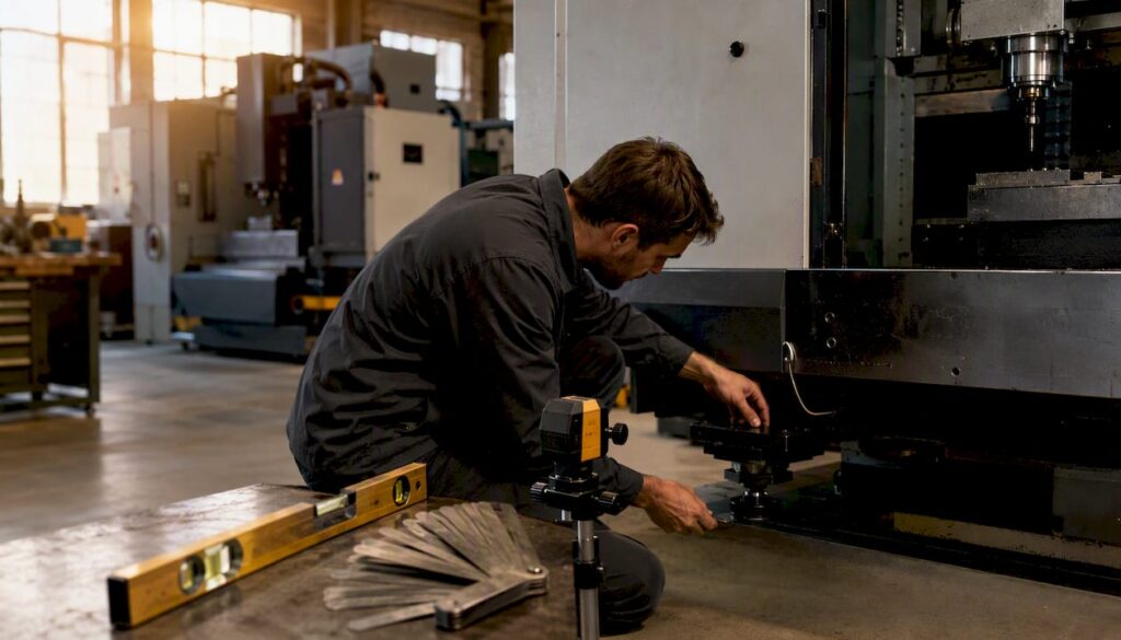
Machine-tool alignment starts with the acceptance question: which geometric errors need checking, under what machine conditions, and against which documented limits? Mechanical instruments and laser systems serve different checks. Ask for a measurement plan that identifies the machine, axes, warm-up state, test method and acceptance criteria before choosing equipment or booking specialist work.
-
Anderson Group Australia — discuss your machine model, installation or observed accuracy issue through our support team. Confirm the available service scope and any specialist calibration requirements before arranging work.
-
Hamar Laser — commercial laser alignment systems with documented 60–70% time savings over traditional toolsets
-
API Metrology / XD-Laser — single-pass 6-DoF capture of the full 21-parameter set in one setup
If your priority is minimal downtime with traceable accuracy, plan a laser single-pass calibration session or contact a local authorised distributor for onsite service.
Key takeaways
Laser single-pass 6-DoF alignment is the fastest and most complete method available for modern CNC machine tool alignment, capturing all 21 geometric error parameters in one setup.
| Point | Details |
|---|---|
| Start with soft foot | Correct soft foot before any other measurement; casting distortion makes all other readings unreliable. |
| Use laser single-pass systems | 6-DoF systems capture up to 21 parameters in one pass, cutting calibration time by around 60–70% versus traditional methods. |
| Verify squareness early | Squareness errors cause skewed holes and parallelogram pockets; check it before applying linear compensation. |
| Schedule regular verification | High-precision machines need quarterly checks; general production machines need surveys every 6–12 months. |
| Choose Australian-supported systems | Specify NATA-traceable calibration and confirm local distributor response times; Anderson provides onsite commissioning across Australia. |
Table of Contents
-
How to choose an alignment system for an Australian workshop
-
What 6-DoF systems and FEA-assisted alignment actually deliver
-
Verification schedule and target tolerances by machine class
Why precise alignment directly affects your bottom line
A misaligned machine does not just produce bad parts. It wears itself out faster, consumes more energy, and fails at the worst possible moment. Bearings, seals, and linear guides all degrade faster when the load path deviates from the designed geometry. Vibration increases, surface finish deteriorates, and spindle runout climbs until scrap rates make the problem impossible to ignore.
The business case for regular CNC machine alignment is straightforward: scrap reduction, fewer unplanned stoppages, and longer component life. Laser calibration services are commonly applied after machine crashes, major rebuilds, and as part of preventive maintenance precisely because axis drift, backlash, and squareness errors accumulate silently until they show up in parts.
Stat callout: Hamar Laser’s commercial systems report alignment downtime reductions of around 60–70% compared with traditional multi-step methods, meaning a full geometric survey that once took a full shift can be completed in a few hours.
After any alignment job, track these outcomes to confirm the work held:
-
Spindle runout (check with a test indicator against a precision ground bar)
-
Part-to-part repeatability on a reference feature
-
Scrap rate on the first production run post-alignment
-
Vibration signature at the spindle (a simple accelerometer reading is enough)
-
Throughput on a timed production cycle
What alignment instruments actually measure
Understanding the error vocabulary lets you read a measurement report and challenge a technician’s recommendations. These are the parameters that matter:
-
Linear positioning error — the deviation of an axis from its commanded position along its own travel direction
-
Straightness — lateral deviation of an axis as it moves (horizontal and vertical components are separate)
-
Pitch, yaw, and roll — angular errors about the three axes as a carriage travels; pitch and yaw show up as angular positioning errors, roll as a twist
-
Squareness (tram) — the perpendicularity between two axes; a squareness error causes drilled holes to lean and milled pockets to be parallelogram-shaped rather than rectangular
-
Flatness — the deviation of a surface or guideway from a true plane
-
Parallelism — the alignment of two features that should be parallel (e.g. spindle axis to column face)
-
Concentricity and spindle axis collinearity — critical for turning centres and boring mills where the spindle and tailstock must share a common axis
-
Backlash — lost motion at axis reversal; relevant for both positioning accuracy and surface finish on direction changes
-
Soft foot — uneven loading of the machine’s support feet, which introduces twist into the casting and corrupts every other measurement
According to precision levelling guidance, the goal of levelling is not geodetic perfection. It is removing twist from the casting and ensuring the geometric relationships of the axes are correct. Absolute level is secondary.
Pro Tip: On a suspect machine, check squareness and soft foot before touching any linear compensation. Soft foot distorts the casting and makes every other reading meaningless. Fix it first, then re-measure.
Alignment methods compared: mechanical versus laser systems
Traditional mechanical methods — precision levels, straight edges, squares, dial indicators, and autocollimators — still work. The problem is that each method addresses one or two parameters at a time, requiring multiple setups and introducing stack-up errors as you move from one check to the next. An autocollimator is excellent for angular errors but tells you nothing about straightness without a separate setup. A precision level catches twist but not squareness. By the time you have worked through the full parameter set, you have accumulated several hours of setup time and a measurement chain where each step’s error feeds into the next.
Laser geometric systems address this directly by measuring multiple parameters simultaneously. A single-pass 6-DoF laser captures linear errors, straightness, pitch, yaw, roll, and squareness in one continuous axis traverse. Live-move capability means you can watch the measurement update in real time as you adjust shims or jack screws, rather than measuring, adjusting, and re-measuring in separate cycles.
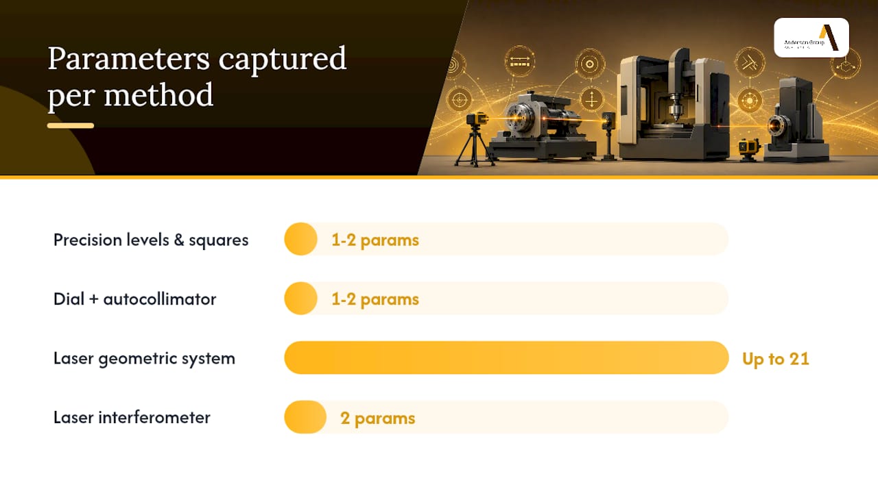
| Method | Parameters captured | Single-pass / live-move | Machine types | Operator skill | Speed | Australian support |
|---|---|---|---|---|---|---|
| Precision levels + squares | Twist, rough squareness | No | All | Moderate | Slow (multi-setup) | Widely available |
| Dial indicators + autocollimator | Angular errors, runout | No | All | High | Slow | Widely available |
| Laser geometric system (e.g. Hamar, API XD-Laser) | Up to 21 parameters (6-DoF) | Yes | 3-axis to 5-axis, gantry, lathe | Moderate (software-guided) | Fast (single pass) | Hamar, API, Acoem Australasia |
| Laser interferometer | Linear positioning, straightness | Partial | Linear axes | High | Moderate | Specialist distributors |
When to use each method:
-
Use mechanical methods for rough commissioning checks, field verification without specialist equipment, or when budget is the binding constraint
-
Use a laser geometric system for full geometric surveys, post-crash checks, and any machine where tolerances tighter than 0.02 mm/m matter
-
Use a laser interferometer when you need traceable linear positioning accuracy to ISO 230-2 or VDI 3441 standards
-
Use a ballbar test (Renishaw QC20-W or equivalent) to assess dynamic performance and servo tuning after geometric alignment is confirmed
Step-by-step alignment workflow for the shop floor
This sequence maps to a real laser alignment session on a vertical machining centre. Adapt the special-case notes for lathes, gantries, and 5-axis machines.
-
Pre-checks and safety — isolate the machine, lock out energy sources, and confirm the floor is thermally stable. Thermal drift during a measurement session corrupts results; allow at least two hours after the machine has been running before starting.
-
Buck-in and reference setup — mount the laser transmitter on a stable instrument stand, not on the machine’s moving table. The Hamar L-743 application note recommends using three reference points to buck in flatness and multiple targets to speed the setup process.
-
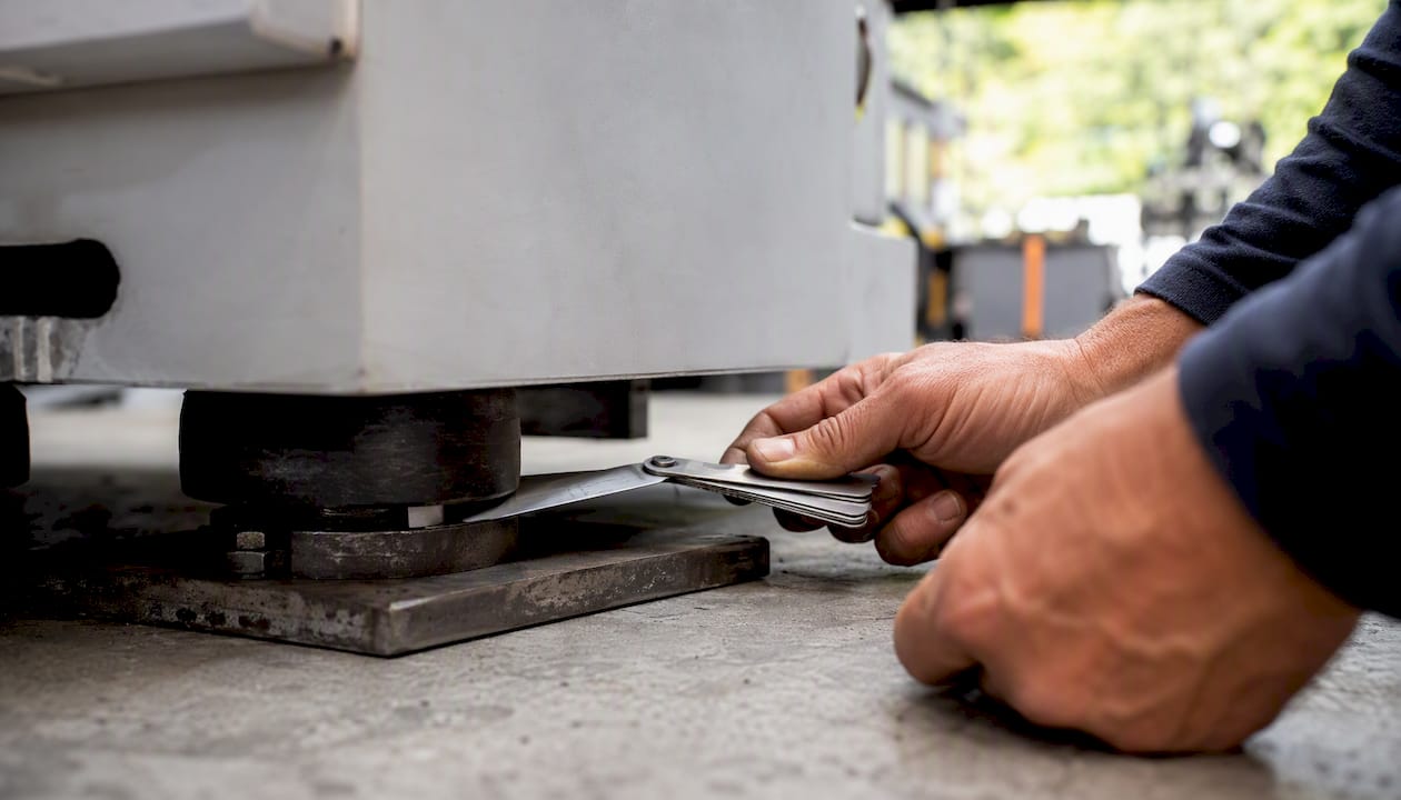
Soft-foot measurement and correction — with the machine on its jack screws, loosen each foot in turn and measure the gap with feeler gauges or the laser system’s soft-foot routine. Correct to less than 0.05 mm before proceeding.
-
Single-pass measurement — traverse each axis at a consistent, slow feed rate while the system records all error parameters. Log the raw data before making any adjustments.
-
Live-move adjustment — with the laser running, adjust jack screws or shims while watching the live display. This is where single-pass systems pay back their cost: you see the effect of each adjustment immediately.
-
Shim insertion and torqueing — once the live-move target is met, insert the calculated shim stack under each foot. Torque fasteners to specification in a cross pattern to avoid re-introducing soft foot.
-
Control measurement — run a full measurement pass after torqueing to confirm the geometry held. This is the pass that goes into the report.
-
Documentation — record all raw data, correction values, shim sizes, torque values, and the control measurement. A signed, dated report with the instrument’s calibration certificate number is the deliverable.
Special cases:
-
Large gantries: check rail parallelism and flatness before squareness; rail errors dominate everything else
-
5-axis rotary axes: measure C-axis and A/B-axis pivot point location separately using a precision sphere and the machine’s probing cycle
-
Lathe tailstock: check tailstock collinearity to the spindle axis in both the horizontal and vertical planes
Pro Tip: Always mount the laser transmitter on an independent instrument stand bolted to the floor, never to the machine table or spindle housing. Any vibration or thermal movement in the machine contaminates the reference beam and invalidates the measurement.
Essential tools and consumables for an alignment job
A complete alignment kit covers measurement, adjustment, and verification. Missing any of these slows the job or forces a return visit.
Measurement equipment:
-
Laser transmitter and sensor/target assembly (e.g. Hamar L-743, API XD-Laser, or Acoem system)
-
Independent instrument stands with fine-adjustment heads
-
Dial test indicators (0.001 mm resolution) for secondary runout and tram checks
-
Precision electronic level (for soft-foot and twist verification)
-
Feeler gauge set (0.02–1.0 mm range)
Adjustment and fixturing:
-
Hydraulic toe jacks or machine jack screws (matched to machine weight)
-
Torque wrench covering the fastener range on the machine’s anchor bolts
-
Magnetic base fixtures for dial indicators
-
Target mounts compatible with the laser system in use
Consumables and spares:
-
Shim assortments in stainless steel (preferred for corrosion resistance): 0.05, 0.10, 0.15, 0.20, 0.25, 0.50, 1.00 mm. Schaeffler’s technical guidance documents layered shim techniques for precise vertical correction and specifies compatible shim sizes for belt and shaft alignment applications
-
Replacement batteries and chargers for the laser system
-
Adhesive retroreflective targets (consumable on most laser systems)
-
Cable ties and protective sleeves for sensor cables
-
Calibration certificate copies for all measurement instruments (keep with the job report)
Store all measurement equipment in its carrying case, away from temperature extremes. Calibration certificates should be current; most laser systems require annual recalibration against a traceable standard.
How to choose an alignment system for an Australian workshop
The right system depends on what you are measuring, how often, and who is doing it. Work through these criteria before committing to a purchase or rental:
-
Parameters captured — does the system measure all the error terms your machine class requires? A 5-axis centre needs rotary axis capability that a basic 3-axis laser system will not provide
-
Single-pass and live-move capability — non-negotiable for high-throughput shops where downtime is expensive
-
Supported machine configurations — confirm the system handles your specific machine geometry (gantry, C-frame, horizontal spindle, etc.)
-
Stated accuracy and traceable calibration — ask for the instrument’s calibration certificate and confirm it references a national standard (NATA-accredited calibration is the benchmark in Australia)
-
Local distributor and support — Acoem Australasia distributes laser geometric alignment tools in Australia and covers long-distance straightness and flatness applications; confirm response times and spare parts availability before buying
-
Training and software usability — software-guided systems reduce the skill barrier, but initial training from the distributor is still worth negotiating into the purchase
-
Accessories availability — shims, targets, and fixtures should be locally stocked, not on a six-week international lead time
-
Price and total cost of ownership — entry-level portable systems start well below the cost of a full interferometer suite; for shops doing fewer than four or five full surveys per year, contracting a calibration service is often more cost-effective than ownership
Pro Tip: When negotiating with a local distributor, ask specifically for Australian case studies and their service-level agreement for instrument repair. A system that takes eight weeks to return from overseas calibration is a liability, not an asset.
For machine commissioning and onsite alignment support, Anderson’s metalwork CNC machinery service capability covers the full range from initial installation through periodic recalibration.
What 6-DoF systems and FEA-assisted alignment actually deliver
The practical advantage of a modern 6-DoF laser system is not just speed. It is completeness. API’s XD-Laser captures all 21 geometric error parameters of a 3-axis machine in a single measurement pass, which means a post-crash check that previously required a full day of multi-step mechanical measurement can be completed in a fraction of that time. For shops running two or three shifts, that difference is measurable in production hours recovered.
Stat callout: Single-pass 6-DoF capture reduces the number of individual setups from multiple (one per parameter group with traditional methods) to one, with real-time feedback during adjustment.
The next development beyond laser measurement is FEA-assisted alignment. Oak Ridge National Laboratory research describes workflows that use finite element models of the machine structure to translate measured misalignments into specific shim thicknesses and support adjustments. Instead of iterating by feel, the technician gets a calculated correction for each support point. The practical result is fewer adjustment cycles and a higher probability of hitting tolerance on the first control measurement.
Pro Tip: FEA-assisted alignment makes economic sense for large, expensive machines where each iteration cycle costs significant downtime — think large gantry machining centres or horizontal boring mills. For a standard VMC, a skilled technician with a good laser system and live-move capability will reach tolerance without it.
Verification schedule and target tolerances by machine class
Alignment is not a one-time event. Machines drift, floors settle, and crashes happen. A practical verification cadence:
-
After commissioning — full geometric survey before the machine enters production
-
After any crash or major repair — full survey before returning to production; laser calibration services are standard practice for this trigger
-
Quarterly — for high-precision work (tolerances tighter than 0.01 mm) or high-cycle machines
-
Every 6–12 months — for general production VMCs, lathes, and routing centres
-
After significant thermal events — if the shop loses climate control in summer or the machine is relocated
Suggested tolerance bands by machine class:
-
VMC, general production: straightness 0.010–0.015 mm per 300 mm, squareness 0.015 mm per 300 mm
-
VMC, precision: straightness 0.005 mm per 300 mm, squareness 0.005 mm per 300 mm
-
Lathe: spindle-to-tailstock collinearity within 0.010 mm over 300 mm of travel
-
Gantry/large machining centre: rail parallelism within 0.020 mm over full travel; squareness 0.015 mm per 1000 mm
-
5-axis centre: rotary axis pivot point location within 0.010 mm; all linear parameters as per VMC precision class
If a measurement exceeds tolerance, do not adjust compensation in the CNC controller as a first response. Compensating for a geometric error in software masks the problem and limits the machine’s full working envelope. Fix the geometry first, then apply compensation only for residual errors within the controller’s correction range.
Pro Tip: Keep a measurement log with trend plots for each axis. Gradual drift is normal; a sudden step change in any parameter is a sign of a mechanical event — a loose anchor bolt, a worn guideway, or a thermal shift in the foundation. Catching it early costs an hour; missing it costs a production run.
An engineer’s perspective on common shop pitfalls
The single most common mistake on the shop floor is skipping the soft-foot check because it feels like a preliminary step rather than a real measurement. It is not preliminary. Soft foot distorts the machine casting and makes every subsequent reading a fiction. Fix it, torque the feet, and then measure.
The second most common error is mounting the laser transmitter on the machine’s own table or spindle housing. The machine is the thing being measured. Attaching the reference instrument to it is like using a ruler made of rubber. Use an independent instrument stand, bolted to the floor away from the machine’s vibration path.
Quick wins you can implement before the next calibration visit: check soft foot with feeler gauges right now, and verify spindle tram with a dial indicator and a precision bar. Neither requires specialist equipment, and both will tell you immediately whether a full laser survey is overdue.
Anderson’s onsite commissioning and alignment services
Anderson Group Australia supplies CNC machinery, servicing and spare parts. Confirm the exact machine configuration, installation arrangements and available support with the team.

Agree installation and acceptance checks for the selected machine. Contact Anderson Australia about available commissioning and service support, and confirm any specialist calibration or training work separately.
Sources
These are the primary references worth bookmarking for product specifications, application notes, and local service contacts:
-
CNC machine tool calibration with API’s XD‑Laser — boosting machining accuracy
-
Oak Ridge National Laboratory research on FEA‑assisted alignment