
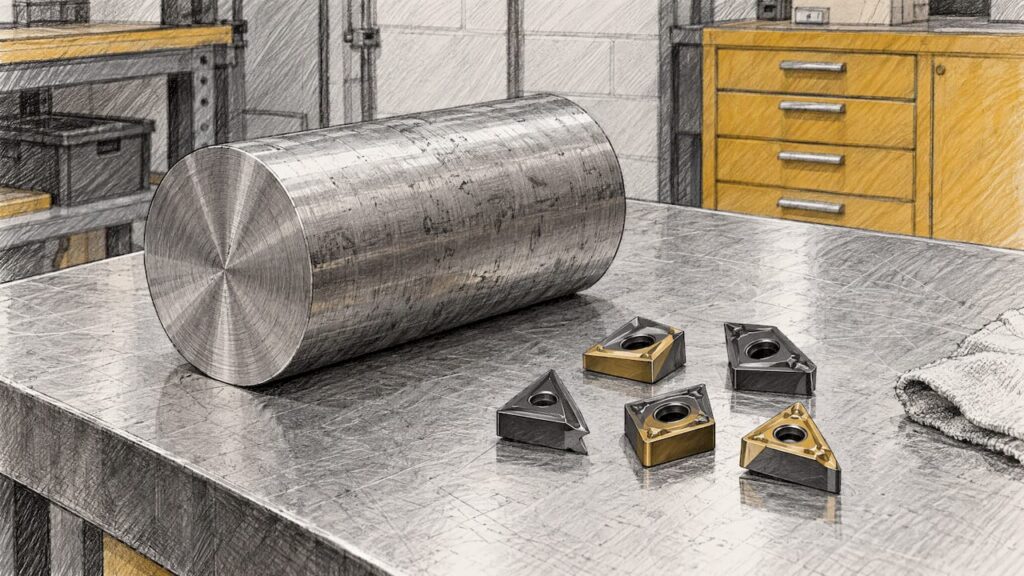
Inconel 718 can be machined on a CNC machining centre, but only with low cutting speeds, a firm chip load, sharp and well-chosen tooling, generous coolant and a rigid machine. The alloy keeps its strength at heat, hardens under the cut and carries heat into the tool instead of the chip. Most of the cost and risk sits in tool life and surface integrity, not in whether the machine can move the axes.
This guide sets out what the published research and tooling guidance say, then turns that into questions to ask when you are specifying a machining centre for your own production. We supply machinery, service and parts. We do not offer subcontract machining, so everything here is for manufacturers who want to cut Inconel in-house.
TL;DR
- Inconel 718 work-hardens, conducts heat poorly and contains abrasive carbides, so tool life, not spindle power alone, decides whether a job is economical.
- For critical parts, Sandvik’s guide caps cutting speed at 60 m/min and says chip thickness should stay at or above 0.1 mm.
- Coolant is not optional in most operations: Sandvik specifies at least 50 L/min for milling and drilling, with ceramic milling the exception.
- Rigid workholding, short tool overhang and controlled tool wear matter as much as the cutting data.
- Confirm coolant delivery, rigidity and configuration against the exact machine model before you buy. Do not assume them from a machine family name.
Table of Contents
- Why Inconel 718 is hard on tools and machines
- Choosing tooling for Inconel 718
- Speeds, feeds and chip thickness
- Coolant and tool paths
- Work hardening, notching and dimensional drift
- Surface finish and accuracy: what moves the result
- Safety and workshop practice in Australia
- What to check before choosing a machine for Inconel
- Talk to us about your Inconel application
- FAQ
- Sources
Why Inconel 718 is hard on tools and machines
Inconel 718 is a precipitation-strengthened nickel superalloy. A University of Bath review explains that its strengthening phases let it retain a large share of its mechanical properties up to 650 °C, which is why it is used in hot, high-stress parts. The same property makes it resist the cutting edge.
A 2023 academic review in Metals lists the problems together: strength at temperature, rapid work hardening, abrasive carbides, poor thermal conductivity and a strong chemical affinity with tool materials. Material can stick to the tool, and high cutting forces can cause vibration and poorer surface quality.
The Bath review links high strength and low thermal conductivity to high cutting forces and temperatures, short tool life and high cost. It cites estimates of about 450 MPa of tool stress and cutting temperatures above 1100 °C. Because the chip carries little of that heat away, much of it stays in the tool and the part.
For a machine buyer, this translates into three demands on the machine:
- Rigidity, so that high cutting forces do not turn into chatter.
- Coolant delivery, so that heat is managed at the edge.
- Process stability over long cycles, so that a worn tool is caught before it damages the part.
This is general guidance drawn from the sources above. It is not a specification of any particular Anderson or Focaseiki model.
Choosing tooling for Inconel 718
Tool choice depends on the stage of the job. Sandvik’s heat-resistant superalloy guide recommends optimised programming to reduce notching, coated carbide grades for last-stage machining of critical parts, and ceramic tools for suitable first and intermediate stages.
Carbide, ceramic and PCBN
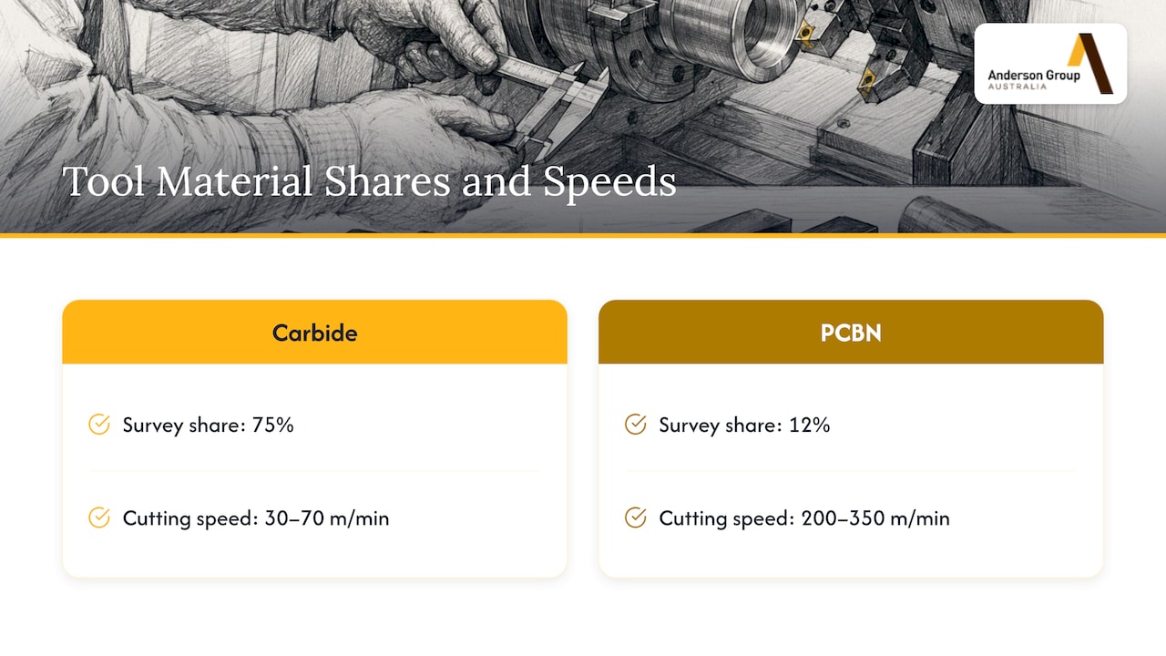
The 2023 Metals review found carbide to be the most common tool material in its surveyed cases, at 75%, with PCBN at 12%. It describes carbide being used at around 30 to 70 m/min and PCBN at around 200 to 350 m/min, depending on the operation and how stable the setup is. Those speed bands show why ceramic and PCBN tooling is tied to very rigid, high-speed setups, while carbide is the everyday choice in general machine shops.
Ceramic milling needs care. Aerospace Manufacturing and Design advises using it for intermediate stock removal only when enough material is left to remove the hardened zone it creates, with a rule of thumb of roughly 0.04 to 0.25 in of retained material, including final wall thickness. Plan the allowance in the program before the first roughing pass, not after.
Edge geometry and wear limits
Sandvik recommends positive cutting-edge geometry, frequent edge indexing and down (climb) milling. It also sets wear limits for critical work: flank wear should not go beyond about 0.2 mm for its R390 example, 0.3 mm for round carbide inserts or 0.6 mm for ceramics. Treat these as reference points and check your own tooling supplier’s data for the insert you actually run.
A practical consequence: tool management becomes part of machine selection. A machine with a generous tool magazine and a reliable way to swap worn tools makes frequent indexing easier to schedule. Whether a particular model offers the magazine size, tool measurement or probing you want must be confirmed for that exact configuration.
Speeds, feeds and chip thickness
Inconel rewards low speed and decisive feed. Cutting too gently is as costly as cutting too fast, because a thin chip rubs instead of cutting.
Sandvik states that for critical parts cutting speed should not exceed 60 m/min and chip thickness should not fall below 0.1 mm. Its approach is a low cutting speed with a moderately high feed per tooth, which holds chip thickness at 0.1 mm or more and helps prevent work hardening.
Machining Doctor, a professional machining data reference, rates Inconel 718 at 10% machinability and about 42 HRC. It suggests sharp positive edges, PVD-coated hard-substrate grades for turning and semi-hard PVD grades for milling.
| Source | Operation | Guidance |
|---|---|---|
| Machining Doctor | Turning | Starting range of 35 to 45 m/min in stable conditions |
| Machining Doctor | Milling | Starting range of 25 to 35 m/min in stable conditions |
| Sandvik | Critical parts | Cutting speed no higher than 60 m/min |
| Sandvik | Critical parts | Chip thickness at least 0.1 mm |
These figures are starting points, not settings for your job. Sandvik notes that heat-treatment condition changes hardness and machining behaviour, so the same alloy supplied solution-treated or aged will not cut the same way. Always take the final data from the tool manufacturer for your insert, your material condition and your machine.
Coolant and tool paths
Coolant volume and pressure
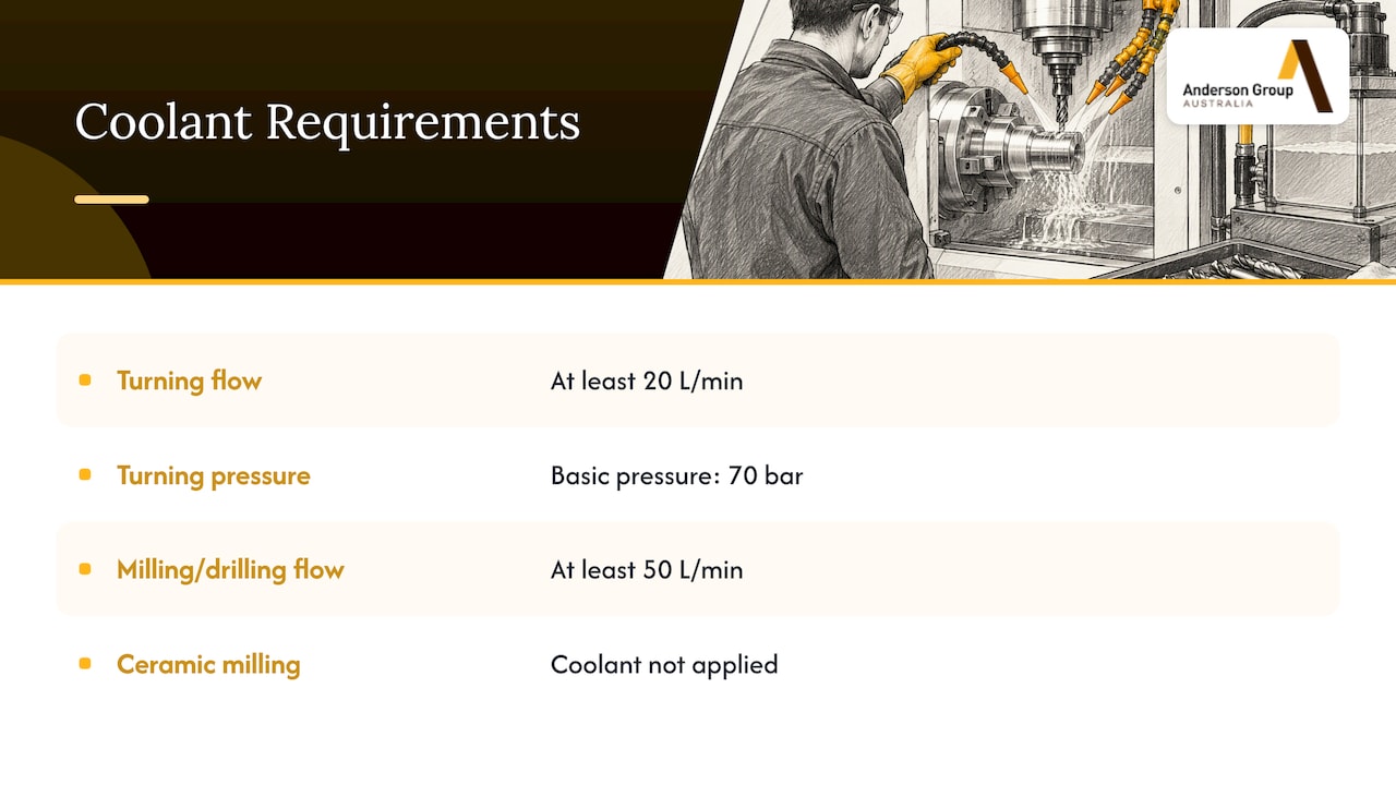
The guidance here is firm. Sandvik says to apply coolant in all operations except ceramic milling, and to use a high-volume, well-directed supply. For turning it specifies at least 20 L/min and a basic pressure of 70 bar, and for milling and drilling at least 50 L/min. The guide also recommends through-spindle coolant where possible and high-pressure coolant for improved tool life.
That has a direct bearing on machine specification. Flood coolant that is adequate for mild steel or aluminium may not deliver those volumes at the edge. Whether high-pressure or through-spindle coolant is available depends on the exact model and configuration. Do not infer it from a family name or an axis count. Ask for the pump pressure and flow rating in writing for the configuration you are quoted. Our guides on 70 to 80 bar high-pressure coolant and what to ask vendors about through-spindle coolant pump pressure explain the questions to put to any supplier.
Liquid coolant for metal is a separate subject from dust extraction on wood and panel machines. Do not carry assumptions from one to the other.
Tool paths for pockets and slots
For pockets and slots, the best-documented approach is to keep the tool engaged lightly and consistently. Sandvik’s entering-angle advice for cuts below 5 mm is an entering angle below 45° and commonly a round positive-rake insert. To reduce notching at the depth-of-cut line, use as small an entering angle as possible and program varying depth of cut so the wear mark does not sit in one place.
Practical points that follow from the sources:
- Use climb milling wherever the program allows.
- Keep tool overhang short and workholding rigid.
- Avoid dwelling or re-cutting the same surface, because that is where work hardening builds.
- Program entry and exit moves that keep chip thickness above the 0.1 mm floor.
CAM strategy is a decision for your programmer and tooling supplier. A controller that handles smooth, continuous tool paths without hesitation helps, but check the controller options on the exact model.
Work hardening, notching and dimensional drift
Work hardening is the heart of the problem. American Machinist reported that a first pass can lift a 34 HRc Inconel 718 surface to about 45 HRc within the first few thousandths, leaving notching at the depth-of-cut line and threatening surface integrity and dimensional precision. That is an older trade-press report, so use it to understand the mechanism and rely on the more recent tool-maker guidance for numbers.
The defences are consistent across sources:
- Keep chip thickness at 0.1 mm or above.
- Keep tools sharp and index inserts before wear passes the limits above.
- Choose a small entering angle or round inserts and vary the depth of cut.
- Take finishing in as few passes as you can, so the cut is not re-entering a hardened layer.
For thin-walled parts, the aerospace guide recommends sharper carbide tooling for semi-finishing, lighter cuts and round tools or inserts. It also advises check passes and probing before final sizing, because stress release can deform the part. If probing matters to your process, confirm that it is available and supported on the specific model and configuration you are considering.
The Bath review adds that Inconel 718 can show dimensional instability after machining, attributed to γ″ phase and machining-induced residual stresses. It also notes that for safety-critical parts, tools may be discarded before their nominal end of life to avoid damage to the surface and subsurface. It presents sensor monitoring of force, vibration, temperature or power as a route to earlier wear and process-control decisions.
For a manufacturer, the message is that cost per part includes inspection and conservative tool changes. Build that into quoting before you commit to a machine.
Surface finish and accuracy: what moves the result
A 2021 Applied Sciences study on milling Inconel 718 found that surface roughness is chiefly affected by cutting speed, feed rate and depth of cut, and that fixture clamping force influences vibration and therefore roughness. It tested target roughness levels of Ra 0.4, 0.6, 0.8 and 1.0 µm.
Its finding on fine finishes is useful for planning: reaching Ra 0.4 to 0.6 µm required reducing feed, while depth of cut became especially important under the tighter surface-quality constraints. This was one research setup, so treat it as an indication of which variables matter rather than a guarantee for your part.
In practice, what you can hold depends on:
- cutting parameters and tool wear,
- machine and fixture rigidity,
- wall thickness and part geometry,
- the heat-treatment condition of the material,
- thermal stability across a long cycle.
We do not publish tolerance or finish guarantees for any machine on this page. Verified specifications are on each product page, and your application should be discussed with us directly so the right model can be checked against it.
Safety and workshop practice in Australia
Nickel alloy machining produces fine swarf, mist and heat, so the shop environment matters as well as the cut. The International Labour Organization’s code on non-ferrous metals industries advises that personal protective equipment is not a substitute for engineering controls. It recommends ventilation that does not recirculate contaminated air, and PPE that is selected, trained for, maintained and replaced to suit the hazard.
In an Australian shop, apply those principles alongside your state or territory work health and safety requirements and the applicable workplace exposure standards. Your WHS regulator and a qualified occupational hygienist can confirm what applies to your coolant, mist and fume situation. The same applies to enclosure, guarding and fire risk when running long unattended cycles.
What to check before choosing a machine for Inconel
Here is a general checklist for specifying a machining centre for nickel alloys. It is general guidance, not a statement that any model meets each point.
- Material and part list. Which alloys (718, 625 or others), which condition, what part sizes and wall thicknesses.
- Operations. Milling, drilling, tapping or a mix. Sandvik’s flow guidance differs between turning and milling or drilling.
- Coolant. Required flow and pressure, and whether through-spindle delivery is offered on the configuration quoted.
- Rigidity and construction. Machine structure, spindle and workholding options suited to high cutting forces.
- Axes. Whether 3-axis or 5-axis access suits your geometry.
- Automation. Whether pallet changing suits your batch pattern, and whether it is offered on that exact model.
- Process monitoring. Probing or sensor options, if you want to catch wear and check thin walls before final sizing.
- Service and parts. What support you need, with scope and response confirmed in writing.
On point 8, we describe service inclusions only where they are documented, so ask us to confirm the agreed scope for your machine.
Where our metal range fits
For metal and aluminium machining, our Focaseiki range is listed on our metal machinery page. It includes vertical machining centres, boxway vertical machining centres, double column machining centres, 5-axis vertical machining centres and models with automatic pallet changers. The 5-axis vertical machining centre and the boxway vertical machining centre are examples of the families to discuss.
The product pages carry the verified specifications. Whether a given model and configuration suits Inconel work is a question for an application discussion, not something to infer from the category. If your part list is about aerospace components, our guide on what engineers must specify for aerospace CNC machining covers the wider specification questions, and our titanium machining guide for shop engineers covers another difficult material with some overlapping concerns.
Talk to us about your Inconel application
We supply CNC machinery, servicing and parts to Australian manufacturers. If you plan to machine nickel alloys in-house, tell us the material, part sizes, operations and volumes, and we will help you work out which metal machining centre to look at and which questions to put to the manufacturer about coolant, configuration and options.
Start with our metal machinery range or browse the machines, then contact us with your application for a quote. We sell machines, service and parts. We do not offer subcontract machining or finished-part manufacturing.
FAQ
What cutting speed should I use for Inconel 718?
Sandvik says cutting speed for critical parts should not exceed 60 m/min. Machining Doctor gives stable-condition starting ranges of 35 to 45 m/min for turning and 25 to 35 m/min for milling. Final values depend on your insert, material condition and machine, so confirm them with your tooling supplier.
Do I need high-pressure or through-spindle coolant?
Sandvik recommends generous, well-directed coolant in all operations except ceramic milling, and suggests through-spindle and high-pressure coolant where possible for better tool life. Availability depends on the exact machine model and configuration. Ask for the pump pressure and flow in writing before you order.
Why does Inconel 718 wear tools so quickly?
It keeps its strength at high temperature, work-hardens, contains abrasive carbides and conducts heat poorly, so the heat stays in the tool. A 2023 academic review also notes that it can stick to tool materials. Holding chip thickness above 0.1 mm and monitoring flank wear are the main controls.
Can a 5-axis machine cut Inconel better than a 3-axis one?
Not automatically. Five-axis access helps with geometry and fewer setups, but the material demands, rigidity, coolant and tooling still apply. Whether pallet changing, probing or specific coolant options exist depends on the exact model, so we confirm those against your application.
Is Inconel machining something you do for customers?
No. We supply the machinery, servicing and parts for manufacturers to machine in their own production. We do not offer subcontract cutting or machining.
Sources
- Pareto Analysis of Machining Factors Significance When Machining Inconel 718 (Metals, 2023)
- Future research directions in the machining of Inconel 718 (University of Bath, 2021)
- Heat resistant super alloys: application guide (Sandvik Coromant)
- Material Inconel 718: machining data sheet (Machining Doctor)
- Essential tips for machining nickel alloys (Aerospace Manufacturing and Design, 2025)
- RX for High-Nickel Anxiety (American Machinist, 2009)
- Optimization of Machining Parameters in Milling Process of Inconel 718 (Applied Sciences, 2021)
- Safety and health in the non-ferrous metals industries (ILO, 2003)